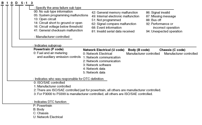
ON-BOARD DIAGNOSTIC [INSTRUMENT CLUSTER]
id092200021843
Outline
Malfunction detection function
DTC No. |
Warning/indicator light |
Description |
Fail-safe function |
Drive cycle |
Self test type*1 |
Memory function |
---|---|---|---|---|---|---|
B11D4:53*2
|
—
|
Laser sensor malfunction
|
×
|
—
|
C, D
|
×
|
C1132:41*8
|
—
|
Malfunction inside instrument cluster
|
—
|
—
|
C, D
|
×
|
U0001:88
|
—
|
Module communication error (HS-CAN)
|
—
|
—
|
C, D
|
×
|
U0010:88
|
—
|
Module communication error (MS-CAN)
|
—
|
—
|
C, D
|
×
|
U0100:00
|
Illuminated/Flash
|
Communication error with PCM
|
—
|
—
|
C, D
|
×
|
U0101:00*3
|
—
|
Communication error with TCM
|
—
|
—
|
C, D
|
×
|
U0104:00*4
|
Illuminate/Flash
|
Communication error with vehicle control module (V/C-module)
|
—
|
—
|
C, D
|
×
|
U0121:00
|
Illuminated/Flash
|
Communication error with ABS HU/CM or DSC HU/CM
|
—
|
—
|
C, D
|
×
|
U0131:00
|
Illuminated/Flash
|
Communication error with EPS control module
|
—
|
—
|
C, D
|
×
|
U0140:00
|
Illuminated/Flash
|
Communication error with front body control module (FBCM)
|
—
|
—
|
C, D
|
×
|
U0142:00
|
—
|
Communication error with rear body control module (RBCM)
|
—
|
—
|
C, D
|
×
|
U0151:00
|
Illuminated/Flash
|
Communication error with SAS control module
|
—
|
—
|
C, D
|
×
|
U0156:00*9
|
Illuminated/Flash
|
Communication error with connectivity master unit (CMU)
|
—
|
—
|
C, D
|
×
|
U0182:00*5
|
Illuminated/Flash
|
Communication error with AFS control module
|
—
|
—
|
C, D
|
×
|
U0214:00
|
Illuminated/Flash
|
Communication error with start stop unit
|
—
|
—
|
C, D
|
×
|
U0232:00*6
|
Illuminated/Flash
|
Communication error with rear vehicle monitoring control module (LH) or BSM control module (LH)
|
—
|
—
|
C, D
|
×
|
U0235:00*2
|
—
|
Communication error with laser sensor
|
×
|
—
|
C, D
|
×
|
U023A:00*7
|
Illuminated/Flash
|
Communication error with forward sensing camera (FSC)
|
—
|
—
|
C, D
|
×
|
U0300:00
|
—
|
Instrument cluster configuration error
|
—
|
—
|
C, D
|
×
|
U0401:68
|
Illuminated/Flash
|
Error signal received from PCM
|
—
|
—
|
C, D
|
×
|
U0402:68*3
|
—
|
Error signal received from transmission/transaxle
|
—
|
—
|
C, D
|
×
|
U0405:00*4
|
Illuminate/Flash
|
Error signal received from vehicle control module (V/C-module)
|
—
|
—
|
C, D
|
×
|
U0422:68
|
Illuminated/Flash
|
Error signal received from front body control module (FBCM)
|
—
|
—
|
C, D
|
×
|
U0433:00*2
|
—
|
Error signal received from laser sensor
|
×
|
—
|
C, D
|
×
|
U0433:68*2
|
—
|
Error signal received from laser sensor
|
×
|
—
|
C, D
|
×
|
U0515:68
|
Illuminated/Flash
|
Error signal received from start stop unit
|
—
|
—
|
C, D
|
×
|
U053B:00*7
|
Illuminated/Flash
|
Error signal received from forward sensing camera (FSC)
|
—
|
—
|
C, D
|
×
|
U2005:86
|
—
|
Error signal received from PCM
|
—
|
—
|
C, D
|
×
|
U2013:13
|
—
|
Cluster switch circuit malfunction
|
—
|
—
|
C, D
|
×
|
U2100:00
|
—
|
Instrument cluster configuration error
|
—
|
—
|
C, D
|
×
|
U2300:41
|
—
|
Instrument cluster configuration error
|
—
|
—
|
C, D
|
×
|
U2300:51
|
—
|
Instrument cluster configuration error
|
—
|
—
|
C, D
|
×
|
U2300:56
|
—
|
Instrument cluster configuration error
|
—
|
—
|
C, D
|
×
|
U2300:57
|
—
|
Instrument cluster configuration error
|
—
|
—
|
C, D
|
×
|
U3000:41
|
—
|
Instrument cluster internal malfunction
|
—
|
—
|
C, D
|
×
|
U3003:16
|
—
|
Low power supply voltage input to instrument cluster
|
—
|
—
|
C, D
|
×
|
DTC 7-digit code definition
am6xun00000789
|
Status byte for DTC
ac5wzn00002008
|
Detection condition for the applicable DTC
DTC No. |
System malfunction location |
Detection condition |
---|---|---|
B11D4:53*1
|
Laser sensor malfunction
|
• The instrument cluster detects any of the following error signals:
|
C1132:41*7
|
Malfunction inside instrument cluster
|
The instrument cluster detects that there is an active driving display malfunction in the instrument cluster.
|
U0001:88
|
Module communication error (HS-CAN)
|
Instrument cluster detects a CAN bus communication line (HS-CAN) malfunction.
|
U0010:88
|
Module communication error (MS-CAN)
|
Instrument cluster detects a CAN bus communication line (MS-CAN) malfunction.
|
U0100:00
|
Communication error with PCM
|
Instrument cluster cannot receive the CAN signal from the PCM.
|
U0101:00*2
|
Communication error with TCM
|
Instrument cluster cannot receive the CAN signal from the TCM for 1 s or more.
|
U0104:00*3
|
Communication error with vehicle control module (V/C-module)
|
Instrument cluster cannot receive the CAN signal from the vehicle control module (V/C-module) for 1 s or more.
|
U0121:00
|
Communication error with DSC HU/CM
|
Instrument cluster cannot receive the CAN signal from the DSC HU/CM for 1 s or more.
|
U0131:00
|
Communication error with EPS control module
|
Instrument cluster cannot receive the CAN signal from the EPS control module for 1 s or more.
|
U0140:00
|
Communication error with front body control module (FBCM)
|
Instrument cluster cannot receive the CAN signal from the front body control module (FBCM) for 5 s or more.
|
U0142:00
|
Communication error with rear body control module (RBCM)
|
Instrument cluster cannot receive the CAN signal from the rear body control module (RBCM) for 5 s or more.
|
U0151:00
|
Communication error with SAS control module
|
Instrument cluster cannot receive the CAN signal from the SAS control module for 2 s or more.
|
U0156:00*8
|
Communication error with connectivity master unit (CMU)
|
Instrument cluster cannot receive the CAN signal from the connectivity master unit (CMU) for 5 s or more.
|
U0182:00*3
|
Communication error with AFS control module
|
Instrument cluster cannot receive the CAN signal from the AFS control module for 5 s or more.
|
U0214:00
|
Communication error with start stop unit
|
Instrument cluster cannot receive the CAN signal from the start stop unit for 5 s or more.
|
U0232:00*4
|
Communication error with rear vehicle monitoring control module (LH) or BSM control module (LH)
|
• Instrument cluster cannot receive the CAN signal from the rear vehicle monitoring control module (LH) for 5 s or more.
• Instrument cluster cannot receive the CAN signal from the BSM control module (LH) for 1.5 s or more.
|
U0235:00*1
|
Communication error with laser sensor
|
Instrument cluster cannot receive the CAN signal from the laser sensor for 1 s or more.
|
U023A:00*5
|
Communication error with forward sensing camera (FSC)
|
Instrument cluster cannot receive the CAN signal from the forward sensing camera (FSC) for 1 s or more.
|
U0300:00
|
Instrument cluster configuration error
|
Instrument cluster configuration error (incorrect value write) detected.
|
U0401:68
|
Error signal received from PCM
|
Instrument cluster receives the error signals from the PCM with the ignition switched ON (engine off or on).
|
U0402:68*2
|
Error signal received from transmission/transaxle
|
Instrument cluster received the error signals from the transmission/transaxle for 1 s or more with the ignition switched ON (engine off or on).
|
U0405:00*3
|
Error signal received from vehicle control module (V/C-module)
|
Instrument cluster receives error signals from the vehicle control module (V/C-module) for 1 s or more with the ignition switched ON (engine off or on).
|
U0422:68
|
Error signal received from front body control module (FBCM)
|
Instrument cluster receives the error signals from the front body control module (FBCM) for 5 s or more with the ignition switched ON (engine off or on).
|
U0433:00*1
|
Error signal received from laser sensor
|
Instrument cluster detects the following conditions:
― Malfunction of laser sensor or smart city brake support related system (laser sensor, DSC HU/CM, PCM)
― Laser sensor control is temporarily inhibited.
|
U0433:68*1
|
Error signal received from laser sensor
|
Instrument cluster detects a malfunction in the laser sensor.
|
U0515:68
|
Error signal received from start stop unit
|
Instrument cluster receives the error signals from the start stop unit with the ignition switched ON (engine off or on).
|
U053B:00*5
|
Error signal received from forward sensing camera (FSC)
|
Instrument cluster receives the error signals from the forward sensing camera (FSC) for 1 s or more with the ignition switched ON (engine off or on).
|
U2005:86
|
Error signal received from PCM
|
Instrument cluster receives the vehicle speed signal error from the PCM for 1 s or more with the ignition switched ON (engine off or on).
|
U2013:13
|
Cluster switch circuit malfunction
|
Instrument cluster detects an open circuit in the cluster switch circuit for 5 s or more with the ignition switched ON (engine off or on).
|
U2100:00
|
Instrument cluster configuration error
|
Instrument cluster configuration error detected as follows:
― No configuration of instrument cluster
― Instrument cluster configuration has not been correctly performed.
|
U2300:41
|
Instrument cluster configuration error
|
Instrument cluster configuration error (data error) detected.
|
U2300:51
|
Instrument cluster configuration error
|
Instrument cluster configuration error (no configuration) detected.
|
U2300:56
|
Instrument cluster configuration error
|
Instrument cluster configuration error (incorrect value write) detected.
|
U2300:57
|
Instrument cluster configuration error
|
Instrument cluster configuration error (data size error) detected.
|
U3000:41
|
Instrument cluster internal malfunction
|
Instrument cluster detects the internal malfunction.
|
U3003:16
|
Low power supply voltage input to instrument cluster
|
Instrument cluster power supply circuit voltage of less than 10V is detected.
|
Snapshot Data
Snapshot data item |
Unit |
Data contents |
Data read/use method |
Corresponding data monitor items |
|
---|---|---|---|---|---|
AAT
|
°C
|
°F
|
Ambient temperature
|
—
|
—
|
APP_STATUS
|
Accelerator Pedal Off/Under20%/Over20%/FAIL
|
Accelerator pedal position status
|
—
|
—
|
|
CFG_STATUS
|
Config Complete/Not Configured/Config Error
|
Instrument cluster configuration status
|
—
|
—
|
|
ECT_STATUS
|
Under 0 degrees C/0 - Under 80 degrees C/Over 80 degrees C/FAIL
|
Engine coolant temperature status
|
—
|
—
|
|
IC_VPWR
|
V
|
Instrument cluster power supply voltage
|
When DTC is detected, instrument cluster displays power supply voltage value of instrument cluster in M-MDS.
|
VPWR
|
|
IG-ON_TIMER
|
hh:mm:ss*1
|
Elapsed time since ignition was switched ON (engine off or on)
|
When DTC is detected, instrument cluster displays elapsed time since ignition was switched ON (engine off or on) in M-MDS.
|
—
|
|
PWR_MODE_KEY
|
Key Out/Key Recently Out (Position 0)/Accessory (Position 1)/Post Ignition (Position 2)/Ignition On (Position 2)/Running (Position 2)/Running - Starting
|
• Key Out: Ignition switched off
• Key Recently Out (Position 0): Elapsed time within 3 s since ignition was switched off
• Accessory (Position 1): Ignition is switched to ACC
• Post Ignition (Position 2): Elapsed time within 3 s since ignition was switched ON (engine off or on)
• Ignition On (Position 2): Ignition switched ON (engine off)
• Running (Position 2): Ignition switched ON (engine on)
• Running - Starting: Cranking condition
|
When DTC is detected, instrument cluster displays ignition switch status in M-MDS.
|
—
|
|
RPM_STATUS
|
Engine Stop/Under1500rpm/Over1500rpm/FAIL
|
Engine speed status
|
When DTC is detected, instrument cluster displays engine speed in M-MDS.
|
TACHOMTR
|
|
SHIFT_STATUS
|
P/N/D/R/FAIL
|
Selector lever position status
|
When DTC is detected, instrument cluster displays selector lever position in M-MDS.
|
—
|
|
TOTAL_DIST
|
km
|
Miles
|
Accumulated total traveled distance from completion of vehicle until instrument cluster detects DTC (Odometer value in instrument cluster)
|
The total traveled distance from which the instrument cluster detects DTCs to the present can be calculated by performing the following procedure.
1. Verify the odometer value in the instrument cluster.
2. Verify the snapshot data item TOTAL_DIST.
3. Subtract 2 from 1.
|
—
|
TOTAL_TIME
|
hh:mm:ss*1
|
Accumulated total elapsed time since vehicle completion until instrument cluster detects a DTC
|
The elapsed time from which the instrument cluster detects DTCs to the present can be calculated by performing the following procedure.
1. Verify the instrument cluster PID item TOTAL_TIME.
2. Verify the snapshot data item TOTAL_TIME.
3. Subtract 2 from 1.
|
TOTAL_TIME
|
|
VPWR
|
V
|
Instrument cluster power supply voltage
|
—
|
VPWR
|
|
VSPD_STATUS
|
Stop/0-10km/h/Over10km/h/FAIL
|
Vehicle speed status
|
When DTC is detected, instrument cluster displays vehicle speed in M-MDS.
|
SPEEDOMTR
|
Data Monitor Function
PID/data monitor table
PID |
Unit/Operation |
Data contents |
Module control terminal |
---|---|---|---|
AFS_ST*1
|
Off/On
|
• Off: AFS not operated
• On: AFS operated
|
B, D (CAN)
|
AT_MAN_M_SW*2
|
Off/On/Unknown
|
• Off: M position switch is off.
• On: M position switch is on.
• Unknown: M position switch signal is not determined.
|
H (M position switch signal)
|
AT_S_DWN_SW*2
|
Off/On/Unknown
|
• Off: Down switch is off.
• On: Down switch is on.
• Unknown: Down switch signal is not determined.
|
G (Down switch signal)
|
AT_S_UP_SW*2
|
Off/On/Unknown
|
• Off: Up switch is off.
• On: Up switch is on.
• Unknown: Up switch signal is not determined.
|
F (UP switch signal)
|
BSM/RVM_SW*3
|
Off/On
|
With blind spot monitoring (BSM) system
• Off: BSM OFF switch is off.
• On: BSM OFF switch is on.
With rear vehicle monitoring system
• Off: RVM switch is off.
• On: RVM switch is on.
|
T, V (BSM OFF/RVM switch operation signal)
|
DSC_OFF_SW
|
Off/On
|
• Off: DSC OFF switch is off.
• On: DSC OFF switch is on.
|
T, V (DSC OFF switch operation signal)
|
FUEL_GAUGE
|
L
|
Displays fuel level detected by the fuel gauge
|
—
|
FUEL_SEN_M
|
ohm
|
Displays fuel gauge sender unit resistance value
|
—
|
FUEL_SEN_S
|
ohm
|
|
—
|
I_ILLUMI_M
|
Off (Day)/On (Night)
|
• Off (Day): TNS switch is off.
• On (Night): TNS switch is on.
|
B, D (CAN)
|
I-ST_OFF_SW*4
|
Off/On
|
• Off: i-stop OFF switch is off.
• On: i-stop OFF switch is on.
|
T, V (i-stop OFF switch operation signal)
|
LDWS_ON_SW*5
|
Off/On
|
• Off: LDWS switch is off.
• On: LDWS switch is on.
|
T, V (LDWS switch operation signal)
|
MULTI_SW_ST
|
O.K./FAULT
|
• O.K.: Cluster switch is normal.
• FAULT: Cluster switch is malfunctioning.
|
T, V (Cluster switch operation signal)
|
ODO_CNT
|
km, ft, mi
|
Displays rolling count of the odometer
|
—
|
P_BRAKE_SW
|
Off/On
|
• Off: Parking brake not applied
• On: Parking brake applied
|
X (Parking brake switch signal)
|
R_GEAR_SW
|
Off/On
|
ATX
• Displays in the M-MDS but it does not operate.
MTX
• Off: Back-up light switch is off.
• On: Back-up light switch is on.
|
B, D (CAN)
|
R_LMP
|
Off/On/Unknown/Fault
|
• Off: Back-up light is turned off.
• On: Back-up light is turned on.
• Unknown: Back-up light signal is not determined.
• Fault: Back-up light malfunction
|
B, D (CAN)
|
SPEEDOMTR
|
KPH, MPH
|
Displays vehicle speed (100 %=300 km/h {186 mph})
|
—
|
TACHOMTR*6
|
RPM
|
Displays engine speed (100 %=10,000 rpm)
|
—
|
TOTAL_TIME
|
hh:mm:ss
|
Displays cumulative elapsed time since vehicle completion
|
—
|
TPMS_CAL_SW*7
|
Off/On
|
• Off: Tire pressure monitoring system (TPMS) set switch is off.
• On: Tire pressure monitoring system (TPMS) set switch is on.
|
T, V (Tire pressure monitoring system (TPMS) set switch status signal)
|
VPWR
|
V
|
Displays power supply voltage
|
S, U (Power supply)
|
Active Command Modes Function
Simulation item |
Unit/Operation |
Data contents |
Output part name |
---|---|---|---|
ALARM
|
On/Off
|
• On: Warning alarm sounds.
• Off: Warning alarm does not sound.
|
Warning alarm (instrument cluster)
|
LCD_SEG
|
Off/On
|
Type A or type C or type D instrument cluster
• Off: Turns off the LCD.
• On: Fully displays LCD.
Type B instrument cluster
• Off: Turns off the LCD.
• On: Illuminates the LCD.
|
LCD
|
SPEEDOMTR*1
|
Off/60 Km/h/120 Km/h
|
• Off: Speedometer needle moves to the bottommost position.
• 60 Km/h: Speedometer needle moves to approx. 61—67 km/h {38—42 mph}.
• 120 Km/h: Speedometer needle moves to approx. 122—130 km/h {75—81 mph}.
|
Speedometer (instrument cluster)
|
TACHOMTR*2
|
Off/3000 RPM/6000 RPM
|
• Off: Tachometer needle moves to bottommost position.
• 3000 RPM: Tachometer needle moves to approx. 3,050 rpm.
• 6000 RPM: Tachometer needle moves to approx. 6,100 rpm.
|
Tachometer (instrument cluster)
|
WL+IL
|
Off/On
|
• Off: Turns off all warning lights, indicator lights.
• On: Illuminates all warning lights, indicator lights.
|
Warning lights, indicator lights (instrument cluster)
|