 |
am3zzn00004836
MULTIPLEX COMMUNICATION SYSTEM
id100000001400
Outline
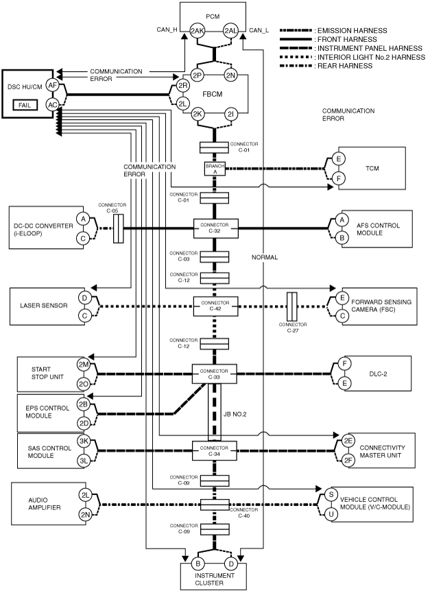
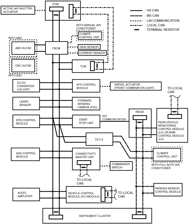
System Wiring Diagram
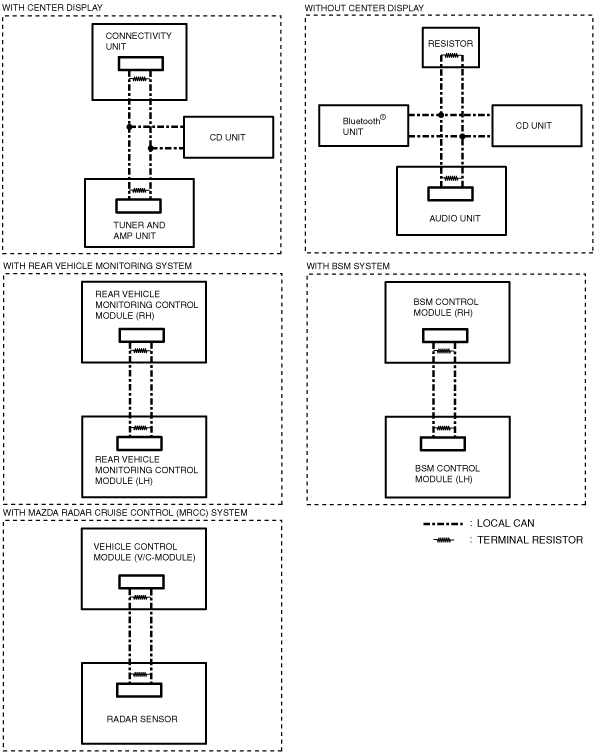
CAN/LIN communication/ISO communication/local CAN
am3zzn00004836
|
Local CAN
am3zzn00004204
|
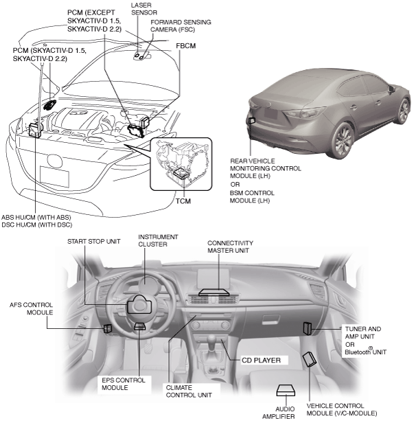
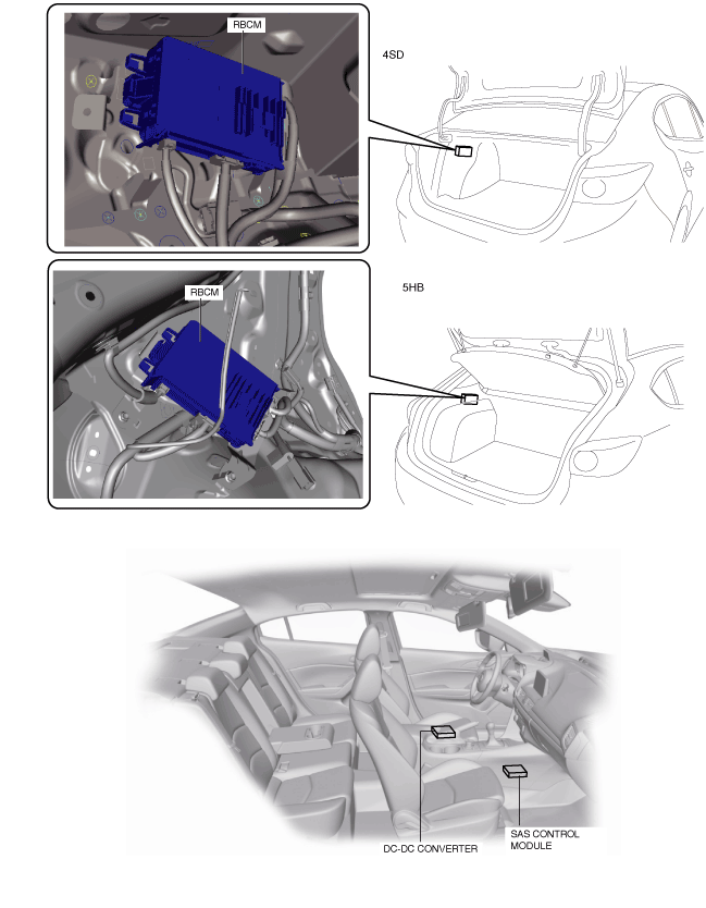
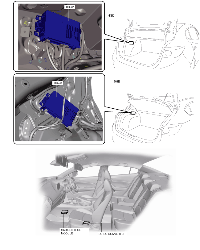
Structural view
L.H.D.
am3zzn00005216
|
L.H.D.
am3zzn00004206
|
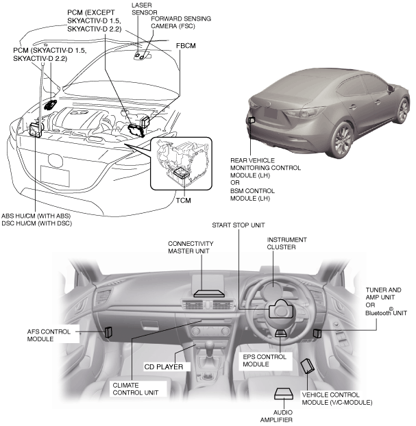
R.H.D.
am3zzn00005217
|
R.H.D.
am3zzn00005218
|
Function
CAN (controller area network) system
HS-CAN communication table
|
Signal |
CAN system related module |
||||||||||||||
|---|---|---|---|---|---|---|---|---|---|---|---|---|---|---|---|
|
PCM |
TCM |
AFS control module |
Laser sensor |
ABS HU/CM (With ABS), DSC HU/CM (With DSC) |
EPS control module |
Front body control module (FBCM) |
Forward sensing camera (FSC) |
Instrument cluster |
Start stop unit |
Vehicle control module (V/C-module) |
SAS control module |
DC-DC converter (i-ELOOP) |
Connectivity master unit |
Audio amplifier |
|
|
Accelerator pedal opening angle
|
OUT
|
–
|
–
|
–
|
IN
|
–
|
–
|
IN
|
IN
|
–
|
IN
|
IN
|
–
|
IN
|
IN
|
|
OUT
|
–
|
–
|
–
|
IN
|
–
|
–
|
IN
|
IN
|
–
|
IN
|
IN
|
–
|
IN
|
–
|
|
|
Accelerator pedal position
|
OUT*1
|
–
|
–
|
IN
|
–
|
–
|
–
|
–
|
–
|
–
|
–
|
–
|
–
|
–
|
–
|
|
Acceleration signal status
|
–
|
–
|
–
|
–
|
IN
|
–
|
–
|
–
|
–
|
–
|
–
|
OUT
|
–
|
–
|
–
|
|
A/C operation signal
|
IN
|
–
|
–
|
–
|
–
|
–
|
–
|
–
|
OUT
|
–
|
–
|
–
|
–
|
IN
|
–
|
|
AFS system warning light status
|
–
|
–
|
OUT
|
–
|
–
|
–
|
–
|
–
|
IN
|
–
|
–
|
–
|
–
|
IN
|
–
|
|
AFS (adaptive front lighting system) level configuration
|
–
|
–
|
OUT
|
–
|
–
|
–
|
–
|
–
|
IN
|
–
|
–
|
–
|
–
|
IN
|
–
|
|
AFS OFF switch status
|
–
|
–
|
IN
|
–
|
–
|
–
|
–
|
–
|
OUT
|
–
|
–
|
–
|
–
|
–
|
–
|
|
Air bag system warning light on request
|
–
|
–
|
–
|
–
|
–
|
–
|
–
|
–
|
IN
|
–
|
–
|
OUT
|
–
|
IN
|
–
|
|
–
|
–
|
–
|
–
|
–
|
–
|
–
|
–
|
OUT
|
–
|
–
|
IN
|
–
|
–
|
–
|
|
|
–
|
–
|
–
|
IN
|
IN
|
–
|
IN
|
–
|
OUT
|
IN
|
IN
|
–
|
–
|
IN
|
–
|
|
|
Air bag system warning buzzer on request
|
–
|
–
|
–
|
–
|
–
|
–
|
–
|
–
|
IN
|
–
|
–
|
OUT
|
–
|
IN
|
–
|
|
Air bag system-related information
|
–
|
–
|
–
|
–
|
–
|
–
|
–
|
–
|
IN
|
–
|
–
|
OUT
|
–
|
IN
|
–
|
|
Air conditioner signal
|
OUT
|
–
|
–
|
–
|
–
|
–
|
IN
|
–
|
IN
|
–
|
–
|
–
|
–
|
–
|
–
|
|
Ambient temperature
|
IN*1
|
IN
|
IN
|
IN
|
IN
|
IN
|
IN
|
–
|
OUT
|
–
|
IN
|
IN
|
–
|
IN
|
–
|
|
OUT
|
–
|
–
|
–
|
IN
|
–
|
–
|
–
|
–
|
–
|
–
|
–
|
–
|
IN
|
–
|
|
|
OUT
|
–
|
IN
|
IN
|
–
|
IN
|
–
|
IN
|
–
|
–
|
–
|
–
|
–
|
IN
|
–
|
|
|
Answer-back-related information
|
–
|
–
|
–
|
–
|
–
|
–
|
IN
|
–
|
OUT
|
–
|
–
|
–
|
–
|
–
|
–
|
|
AT shift position
|
IN
|
OUT*1
|
–
|
–
|
–
|
–
|
–
|
–
|
–
|
–
|
–
|
–
|
–
|
–
|
–
|
|
ATX gear position
|
IN
|
OUT*1
|
–
|
–
|
IN
|
–
|
IN
|
IN
|
IN
|
IN
|
IN
|
–
|
–
|
IN
|
–
|
|
OUT*3
|
–
|
–
|
–
|
IN
|
–
|
IN
|
IN
|
IN
|
IN
|
IN
|
–
|
–
|
IN
|
–
|
|
|
IN
|
OUT*1
|
–
|
–
|
–
|
–
|
–
|
–
|
IN
|
–
|
IN
|
–
|
–
|
IN
|
–
|
|
|
OUT*3
|
–
|
–
|
–
|
–
|
–
|
–
|
–
|
IN
|
–
|
IN
|
–
|
–
|
IN
|
–
|
|
|
IN
|
OUT*1
|
–
|
–
|
–
|
–
|
–
|
–
|
IN
|
–
|
–
|
–
|
–
|
IN
|
–
|
|
|
OUT*3
|
–
|
–
|
–
|
–
|
–
|
–
|
–
|
IN
|
–
|
–
|
–
|
–
|
IN
|
–
|
|
|
Audio configuration information
|
–
|
–
|
–
|
–
|
–
|
–
|
–
|
–
|
OUT
|
–
|
–
|
–
|
–
|
IN
|
–
|
|
Back-up light on request
|
–
|
–
|
IN
|
IN
|
IN
|
–
|
–
|
–
|
OUT
|
–
|
–
|
–
|
–
|
IN
|
–
|
|
Back-up light switch
|
OUT
|
–
|
–
|
–
|
IN
|
–
|
–
|
IN
|
IN
|
–
|
IN
|
–
|
–
|
IN
|
–
|
|
Battery charge status
|
IN*1
|
–
|
IN
|
IN
|
IN
|
IN
|
IN
|
–
|
OUT
|
IN
|
IN
|
IN
|
–
|
IN
|
–
|
|
Battery regeneration status
|
OUT*1
|
–
|
–
|
–
|
–
|
–
|
–
|
–
|
IN
|
–
|
–
|
–
|
–
|
IN
|
–
|
|
Blower motor relay status
|
–
|
–
|
–
|
–
|
–
|
–
|
OUT
|
–
|
IN
|
–
|
–
|
–
|
–
|
–
|
–
|
|
Blower relay on request
|
–
|
–
|
–
|
–
|
–
|
–
|
IN
|
–
|
OUT
|
–
|
–
|
–
|
–
|
–
|
–
|
|
Blower speed
|
IN
|
–
|
–
|
–
|
–
|
–
|
OUT
|
–
|
–
|
–
|
–
|
–
|
–
|
IN
|
–
|
|
Brake fluid level
|
–
|
–
|
–
|
–
|
–
|
–
|
OUT
|
–
|
IN
|
–
|
IN
|
–
|
–
|
IN
|
–
|
|
Brake light status
|
–
|
–
|
–
|
–
|
IN
|
–
|
–
|
–
|
OUT
|
–
|
IN
|
–
|
–
|
IN
|
–
|
|
Brake pedal depressed status
|
OUT*1
|
–
|
–
|
IN
|
–
|
–
|
–
|
–
|
–
|
–
|
–
|
–
|
–
|
–
|
–
|
|
Brake status
|
–
|
–
|
–
|
–
|
OUT
|
–
|
–
|
–
|
–
|
–
|
IN
|
–
|
–
|
–
|
–
|
|
Brake switch (No.1 signal)
|
OUT
|
IN
|
–
|
–
|
IN
|
–
|
IN
|
IN
|
IN
|
–
|
–
|
–
|
–
|
IN
|
–
|
|
Brake switch (No.2 signal)
|
OUT
|
IN
|
–
|
–
|
–
|
–
|
–
|
IN
|
IN
|
IN
|
IN
|
IN
|
–
|
IN
|
–
|
|
OUT
|
–
|
–
|
–
|
–
|
–
|
–
|
–
|
–
|
IN
|
–
|
–
|
–
|
–
|
–
|
|
|
Brake switch malfunction determination
|
OUT
|
–
|
–
|
–
|
–
|
–
|
–
|
–
|
IN
|
–
|
–
|
–
|
–
|
IN
|
–
|
|
Brake switch status
|
OUT*1
|
–
|
–
|
IN
|
–
|
–
|
–
|
–
|
–
|
–
|
–
|
–
|
–
|
–
|
–
|
|
BSM system personalization-related information
|
–
|
–
|
–
|
–
|
–
|
–
|
–
|
–
|
IN
|
–
|
–
|
–
|
–
|
OUT
|
–
|
|
–
|
–
|
–
|
–
|
–
|
–
|
–
|
–
|
OUT
|
–
|
–
|
–
|
–
|
IN
|
–
|
|
|
Clutch pedal stroke sensor
|
OUT
|
–
|
–
|
–
|
IN
|
–
|
–
|
–
|
–
|
–
|
–
|
–
|
–
|
–
|
–
|
|
Clutch status
|
OUT*1
|
–
|
–
|
–
|
–
|
–
|
–
|
–
|
–
|
–
|
–
|
–
|
–
|
IN
|
–
|
|
Cluster switch status
|
–
|
–
|
IN
|
–
|
–
|
–
|
–
|
IN
|
OUT
|
–
|
IN
|
–
|
–
|
–
|
–
|
|
Combiner current position signal
|
–
|
–
|
–
|
–
|
–
|
–
|
–
|
–
|
IN
|
–
|
–
|
–
|
–
|
OUT
|
–
|
|
Combiner target angle signal
|
–
|
–
|
–
|
–
|
–
|
–
|
–
|
–
|
IN
|
–
|
–
|
–
|
–
|
OUT
|
–
|
|
Combiner autodimming level signal
|
–
|
–
|
–
|
–
|
–
|
–
|
–
|
–
|
IN
|
–
|
–
|
–
|
–
|
OUT
|
–
|
|
Combiner dimming switch signal
|
–
|
–
|
–
|
–
|
–
|
–
|
–
|
–
|
IN
|
–
|
–
|
–
|
–
|
OUT
|
–
|
|
Combiner manual-dimming level signal
|
–
|
–
|
–
|
–
|
–
|
–
|
–
|
–
|
IN
|
–
|
–
|
–
|
–
|
OUT
|
–
|
|
Collision detection (front, side, roll over)
|
IN
|
–
|
–
|
–
|
IN
|
–
|
IN
|
–
|
–
|
–
|
–
|
OUT
|
–
|
IN
|
–
|
|
Collision detection (rear)
|
IN
|
–
|
–
|
–
|
IN
|
–
|
IN
|
–
|
–
|
–
|
–
|
OUT
|
–
|
IN
|
–
|
|
Cranking start
|
IN
|
–
|
–
|
–
|
–
|
–
|
IN
|
–
|
IN
|
OUT
|
–
|
–
|
–
|
–
|
–
|
|
Cranking time
|
OUT
|
–
|
–
|
–
|
–
|
–
|
–
|
–
|
–
|
IN
|
–
|
–
|
–
|
IN
|
–
|
|
Cruise control control status
|
OUT*1
|
–
|
–
|
–
|
IN
|
–
|
–
|
–
|
–
|
–
|
IN
|
–
|
–
|
–
|
–
|
|
Cruise control set speed
|
OUT*1
|
–
|
–
|
–
|
IN
|
–
|
–
|
–
|
–
|
–
|
IN
|
–
|
–
|
–
|
–
|
|
Cruise control switch
|
OUT*1
|
–
|
–
|
–
|
IN
|
–
|
–
|
–
|
–
|
–
|
IN
|
–
|
–
|
–
|
–
|
|
Cruise control switch signal
|
IN
|
–
|
–
|
–
|
IN
|
–
|
–
|
–
|
–
|
OUT
|
IN
|
–
|
–
|
–
|
–
|
|
IN
|
–
|
–
|
–
|
–
|
–
|
–
|
–
|
–
|
OUT
|
IN
|
–
|
–
|
–
|
–
|
|
|
OUT
|
–
|
–
|
–
|
–
|
–
|
–
|
–
|
IN
|
IN
|
–
|
–
|
–
|
IN
|
–
|
|
|
Cruise control system-related information
|
IN*1
|
–
|
–
|
–
|
IN
|
–
|
–
|
–
|
–
|
–
|
OUT
|
–
|
–
|
IN
|
–
|
|
–
|
–
|
–
|
–
|
–
|
–
|
–
|
–
|
IN
|
–
|
OUT
|
–
|
–
|
IN
|
–
|
|
|
IN*1
|
–
|
–
|
OUT
|
–
|
–
|
–
|
–
|
–
|
–
|
–
|
–
|
–
|
IN
|
–
|
|
|
IN*1
|
–
|
–
|
–
|
OUT
|
–
|
–
|
–
|
–
|
–
|
IN
|
–
|
–
|
–
|
–
|
|
|
–
|
–
|
–
|
–
|
OUT
|
–
|
–
|
–
|
–
|
–
|
IN
|
–
|
–
|
–
|
–
|
|
|
OUT*1
|
–
|
–
|
–
|
IN
|
–
|
–
|
–
|
–
|
–
|
IN
|
–
|
–
|
–
|
–
|
|
|
–
|
–
|
–
|
OUT
|
–
|
–
|
–
|
–
|
IN
|
–
|
–
|
–
|
–
|
IN
|
–
|
|
|
–
|
–
|
–
|
OUT
|
–
|
–
|
–
|
–
|
IN
|
–
|
–
|
–
|
–
|
–
|
–
|
|
|
–
|
–
|
–
|
OUT
|
IN
|
–
|
–
|
–
|
IN
|
–
|
IN
|
–
|
–
|
IN
|
–
|
|
|
–
|
–
|
–
|
OUT
|
IN
|
–
|
–
|
–
|
IN
|
–
|
–
|
–
|
–
|
–
|
–
|
|
|
–
|
–
|
–
|
OUT
|
–
|
–
|
–
|
–
|
IN
|
–
|
IN
|
–
|
–
|
IN
|
–
|
|
|
DC-DC converter condition
|
IN*1
|
–
|
–
|
–
|
–
|
–
|
OUT
|
–
|
–
|
–
|
–
|
–
|
–
|
–
|
–
|
|
Diesel particulate filter warning light
|
OUT*2
|
–
|
–
|
–
|
–
|
–
|
–
|
–
|
IN
|
–
|
–
|
–
|
–
|
IN
|
–
|
|
Dimmer cancel
|
–
|
–
|
–
|
–
|
–
|
–
|
–
|
–
|
OUT
|
IN
|
–
|
–
|
–
|
IN
|
–
|
|
Distance unit switch signal
|
–
|
–
|
–
|
–
|
–
|
–
|
–
|
–
|
IN
|
–
|
–
|
–
|
–
|
OUT
|
–
|
|
Door status
|
IN*1
|
–
|
–
|
–
|
–
|
–
|
–
|
–
|
OUT
|
IN
|
–
|
–
|
–
|
IN
|
–
|
|
IN*1
|
–
|
–
|
–
|
–
|
–
|
–
|
–
|
OUT
|
–
|
–
|
–
|
–
|
IN
|
IN
|
|
|
–
|
–
|
–
|
–
|
–
|
–
|
–
|
–
|
OUT
|
–
|
–
|
–
|
–
|
IN
|
IN
|
|
|
–
|
–
|
–
|
–
|
–
|
–
|
–
|
–
|
OUT
|
–
|
–
|
–
|
–
|
IN
|
–
|
|
|
Driving condition
|
IN*1
|
–
|
IN
|
IN
|
IN
|
IN
|
IN
|
–
|
OUT
|
IN
|
IN
|
IN
|
–
|
IN
|
–
|
|
Driver-side buckle switch status
|
IN*1
|
–
|
–
|
–
|
–
|
–
|
–
|
–
|
IN
|
IN
|
–
|
OUT
|
–
|
IN
|
–
|
|
DSC OFF switch status
|
IN*3
|
–
|
–
|
–
|
IN
|
–
|
–
|
–
|
OUT
|
–
|
–
|
–
|
–
|
–
|
–
|
|
ABS system-related information
(With ABS), DSC system-related information (With DSC)
|
OUT
|
–
|
–
|
–
|
IN
|
–
|
–
|
–
|
–
|
–
|
–
|
–
|
–
|
–
|
–
|
|
IN
|
–
|
–
|
–
|
OUT
|
–
|
–
|
–
|
–
|
–
|
–
|
–
|
–
|
–
|
–
|
|
|
IN
|
IN
|
–
|
–
|
OUT
|
IN
|
IN
|
IN
|
–
|
–
|
IN
|
IN
|
–
|
IN
|
–
|
|
|
–
|
–
|
–
|
–
|
OUT
|
–
|
–
|
–
|
–
|
–
|
–
|
–
|
–
|
IN
|
–
|
|
|
IN
|
IN
|
–
|
–
|
OUT
|
IN
|
–
|
IN
|
–
|
–
|
IN
|
IN
|
–
|
IN
|
–
|
|
|
IN
|
IN
|
–
|
–
|
OUT
|
IN
|
–
|
IN
|
–
|
–
|
IN
|
–
|
–
|
IN
|
–
|
|
|
IN
|
IN
|
–
|
–
|
OUT
|
–
|
–
|
IN
|
–
|
–
|
IN
|
–
|
–
|
IN
|
–
|
|
|
IN
|
IN
|
–
|
–
|
OUT
|
–
|
–
|
–
|
–
|
–
|
–
|
–
|
–
|
IN
|
–
|
|
|
IN
|
–
|
–
|
–
|
OUT
|
–
|
–
|
–
|
–
|
–
|
IN
|
–
|
–
|
IN
|
–
|
|
|
IN
|
IN
|
–
|
–
|
OUT
|
–
|
IN
|
–
|
–
|
–
|
IN
|
–
|
–
|
IN
|
–
|
|
|
–
|
IN
|
–
|
–
|
OUT
|
–
|
–
|
–
|
IN
|
–
|
IN
|
–
|
–
|
IN
|
–
|
|
|
–
|
–
|
–
|
–
|
OUT
|
–
|
–
|
–
|
IN
|
–
|
IN
|
–
|
–
|
IN
|
–
|
|
|
–
|
–
|
–
|
–
|
OUT
|
–
|
–
|
–
|
IN
|
–
|
–
|
–
|
–
|
IN
|
–
|
|
|
IN*3
|
IN
|
–
|
–
|
OUT
|
–
|
–
|
–
|
–
|
–
|
IN
|
–
|
–
|
–
|
–
|
|
|
–
|
–
|
–
|
–
|
OUT
|
–
|
–
|
–
|
IN
|
–
|
–
|
–
|
–
|
IN
|
–
|
|
|
–
|
–
|
–
|
–
|
OUT
|
–
|
IN
|
–
|
–
|
–
|
–
|
–
|
–
|
IN
|
–
|
|
|
Electric AT oil pump-related signal (i-stop)
|
IN
|
OUT*1
|
–
|
–
|
–
|
–
|
–
|
–
|
–
|
–
|
–
|
–
|
–
|
–
|
–
|
|
Engine coolant temperature
|
OUT
|
–
|
–
|
–
|
–
|
–
|
IN
|
–
|
IN
|
–
|
–
|
–
|
–
|
IN
|
–
|
|
Engine displacement
|
OUT
|
IN
|
–
|
–
|
IN
|
IN
|
IN
|
–
|
IN
|
–
|
IN
|
–
|
–
|
IN
|
IN
|
|
OUT
|
–
|
–
|
–
|
IN
|
–
|
–
|
–
|
IN
|
–
|
–
|
–
|
–
|
–
|
IN
|
|
|
Engine off time
|
IN
|
–
|
–
|
–
|
–
|
–
|
–
|
–
|
–
|
OUT
|
–
|
–
|
–
|
–
|
–
|
|
IN
|
IN
|
–
|
–
|
–
|
–
|
–
|
–
|
OUT
|
–
|
–
|
–
|
–
|
IN
|
–
|
|
|
Engine Status
|
OUT
|
IN
|
–
|
–
|
–
|
–
|
–
|
–
|
IN
|
–
|
–
|
–
|
–
|
IN
|
–
|
|
OUT
|
–
|
–
|
–
|
–
|
–
|
–
|
–
|
IN
|
–
|
–
|
–
|
–
|
–
|
–
|
|
|
OUT*1
|
–
|
–
|
IN
|
–
|
–
|
–
|
–
|
–
|
–
|
–
|
–
|
–
|
–
|
–
|
|
|
OUT
|
–
|
–
|
IN
|
–
|
–
|
–
|
–
|
IN
|
–
|
–
|
–
|
–
|
IN
|
–
|
|
|
OUT
|
–
|
–
|
IN
|
–
|
–
|
–
|
–
|
IN
|
–
|
–
|
–
|
–
|
–
|
–
|
|
|
OUT
|
–
|
–
|
–
|
–
|
–
|
–
|
–
|
–
|
IN
|
–
|
–
|
–
|
IN
|
–
|
|
|
–
|
–
|
–
|
–
|
OUT
|
–
|
–
|
–
|
–
|
–
|
IN
|
–
|
–
|
–
|
–
|
|
|
Engine speed
|
OUT
|
–
|
–
|
–
|
IN
|
IN
|
IN
|
IN
|
IN
|
IN
|
IN
|
IN
|
–
|
IN
|
IN
|
|
OUT*1
|
IN
|
–
|
–
|
–
|
–
|
–
|
–
|
–
|
–
|
–
|
–
|
–
|
–
|
–
|
|
|
Engine status at idle
|
OUT
|
–
|
–
|
–
|
–
|
–
|
–
|
–
|
IN
|
–
|
–
|
–
|
–
|
–
|
–
|
|
Engine stop request
|
IN*1
|
–
|
–
|
–
|
–
|
–
|
–
|
–
|
OUT
|
–
|
–
|
–
|
–
|
IN
|
–
|
|
Engine torque
|
OUT
|
–
|
–
|
–
|
–
|
–
|
IN
|
–
|
–
|
–
|
–
|
–
|
–
|
–
|
–
|
|
OUT
|
–
|
–
|
–
|
IN
|
–
|
–
|
–
|
–
|
–
|
–
|
–
|
–
|
–
|
–
|
|
|
EPS status
|
IN*1
|
–
|
–
|
–
|
–
|
OUT
|
–
|
–
|
–
|
–
|
–
|
–
|
–
|
IN
|
–
|
|
–
|
–
|
–
|
–
|
–
|
OUT
|
–
|
–
|
IN
|
–
|
–
|
–
|
–
|
IN
|
–
|
|
|
–
|
–
|
–
|
–
|
–
|
OUT
|
–
|
–
|
–
|
–
|
–
|
–
|
–
|
IN
|
–
|
|
|
Forward sensing camera (FSC) personalization-related information
|
–
|
–
|
–
|
–
|
–
|
–
|
–
|
OUT
|
–
|
–
|
IN
|
–
|
–
|
–
|
–
|
|
–
|
–
|
–
|
–
|
–
|
–
|
–
|
–
|
–
|
OUT
|
–
|
–
|
–
|
IN
|
–
|
|
|
–
|
–
|
–
|
–
|
–
|
–
|
–
|
IN
|
–
|
–
|
–
|
–
|
–
|
OUT
|
–
|
|
|
–
|
–
|
–
|
–
|
–
|
–
|
–
|
OUT
|
–
|
–
|
–
|
–
|
–
|
IN
|
–
|
|
|
–
|
–
|
–
|
–
|
–
|
–
|
–
|
–
|
–
|
–
|
OUT
|
–
|
–
|
IN
|
–
|
|
|
Front combination light on request
|
–
|
–
|
–
|
–
|
–
|
–
|
IN
|
OUT
|
–
|
–
|
IN
|
–
|
–
|
–
|
–
|
|
Front fog light information
|
–
|
–
|
–
|
–
|
–
|
–
|
OUT
|
IN
|
IN
|
–
|
–
|
–
|
–
|
IN
|
–
|
|
Fuel cap warning light on request
|
OUT
|
–
|
–
|
–
|
–
|
–
|
–
|
–
|
IN
|
–
|
–
|
–
|
–
|
IN
|
–
|
|
Fuel cut request
|
IN
|
–
|
–
|
–
|
–
|
–
|
IN
|
–
|
IN
|
–
|
–
|
OUT
|
–
|
IN
|
–
|
|
IN
|
–
|
–
|
–
|
IN
|
–
|
–
|
–
|
–
|
–
|
–
|
OUT
|
–
|
–
|
–
|
|
|
Fuel economy information reset request signal
|
–
|
–
|
–
|
–
|
–
|
–
|
–
|
–
|
IN
|
–
|
–
|
–
|
–
|
OUT
|
–
|
|
Fuel injection amount
|
OUT
|
–
|
–
|
–
|
–
|
–
|
–
|
–
|
IN
|
–
|
–
|
–
|
–
|
IN
|
–
|
|
Fuel tank level
|
IN
|
–
|
–
|
–
|
–
|
–
|
–
|
–
|
OUT*2
|
–
|
–
|
–
|
–
|
IN
|
–
|
|
IN
|
–
|
–
|
–
|
–
|
–
|
–
|
–
|
OUT
|
–
|
–
|
–
|
–
|
IN
|
–
|
|
|
Gear position
|
OUT
|
–
|
–
|
–
|
–
|
–
|
–
|
–
|
IN
|
–
|
–
|
–
|
–
|
IN
|
–
|
|
OUT
|
–
|
–
|
–
|
–
|
–
|
–
|
–
|
IN
|
–
|
–
|
–
|
–
|
–
|
–
|
|
|
Global central configuration
|
IN
|
IN
|
IN
|
IN
|
IN
|
IN
|
–
|
–
|
OUT
|
IN
|
IN
|
–
|
–
|
IN
|
IN
|
|
Global central configuration error
|
OUT
|
–
|
–
|
–
|
–
|
–
|
–
|
–
|
IN
|
–
|
–
|
–
|
–
|
IN
|
–
|
|
Hands-free telephone system-related information
|
–
|
IN
|
–
|
–
|
IN
|
–
|
–
|
–
|
OUT
|
IN
|
IN
|
–
|
–
|
IN
|
–
|
|
Hazard warning switch information
|
–
|
–
|
–
|
–
|
–
|
–
|
IN
|
IN
|
IN
|
OUT
|
IN
|
–
|
–
|
–
|
–
|
|
Headlight information
|
IN*1
|
–
|
IN
|
–
|
–
|
–
|
OUT
|
IN
|
IN
|
–
|
IN
|
–
|
–
|
IN
|
–
|
|
Headlight warning request signal
|
–
|
–
|
–
|
–
|
–
|
–
|
OUT
|
–
|
IN
|
–
|
–
|
–
|
–
|
IN
|
–
|
|
Headlight status
|
–
|
–
|
–
|
–
|
–
|
–
|
OUT
|
IN
|
–
|
–
|
–
|
–
|
–
|
IN
|
–
|
|
High-beam indicator
|
–
|
–
|
–
|
–
|
–
|
–
|
OUT
|
IN
|
IN
|
–
|
–
|
–
|
–
|
IN
|
–
|
|
High-beam control personalization-related information
|
–
|
–
|
–
|
–
|
–
|
–
|
–
|
–
|
IN
|
–
|
–
|
–
|
–
|
OUT
|
–
|
|
Horn control
|
–
|
–
|
–
|
–
|
–
|
–
|
IN
|
–
|
–
|
OUT
|
–
|
–
|
–
|
–
|
–
|
|
Hood status
|
IN*1
|
–
|
–
|
–
|
–
|
–
|
–
|
–
|
OUT
|
IN
|
–
|
–
|
IN
|
IN
|
–
|
|
i-ELOOP-related information
|
IN*1
|
IN
|
–
|
–
|
–
|
–
|
–
|
–
|
–
|
–
|
–
|
–
|
OUT
|
IN
|
–
|
|
IN*1
|
–
|
–
|
–
|
–
|
–
|
–
|
–
|
–
|
–
|
–
|
–
|
OUT
|
–
|
–
|
|
|
OUT*1
|
IN
|
–
|
–
|
–
|
–
|
–
|
–
|
–
|
–
|
–
|
–
|
IN
|
IN
|
–
|
|
|
OUT*1
|
IN
|
–
|
–
|
–
|
–
|
–
|
–
|
IN
|
–
|
–
|
–
|
IN
|
IN
|
–
|
|
|
IN*1
|
–
|
–
|
–
|
–
|
–
|
–
|
–
|
–
|
–
|
–
|
–
|
OUT
|
–
|
–
|
|
|
Ignition key status
|
IN*1
|
–
|
IN
|
IN
|
IN
|
IN
|
IN
|
–
|
OUT
|
IN
|
IN
|
IN
|
–
|
IN
|
–
|
|
Ignition off timer
|
IN*1
|
IN
|
IN
|
IN
|
IN
|
IN
|
IN
|
–
|
OUT
|
IN
|
IN
|
IN
|
–
|
IN
|
–
|
|
Ignition switch status
|
–
|
–
|
–
|
–
|
–
|
–
|
OUT
|
–
|
IN
|
–
|
–
|
–
|
–
|
IN
|
–
|
|
–
|
–
|
IN
|
–
|
–
|
IN
|
IN
|
IN
|
OUT
|
–
|
IN
|
–
|
–
|
IN
|
IN
|
|
|
Immobilizer system related information
|
OUT
|
–
|
–
|
–
|
–
|
–
|
–
|
–
|
–
|
IN
|
–
|
–
|
–
|
–
|
–
|
|
IN
|
–
|
–
|
–
|
–
|
–
|
–
|
–
|
–
|
OUT
|
–
|
–
|
–
|
–
|
–
|
|
|
Instrument cluster personalization-related information
|
–
|
–
|
–
|
–
|
–
|
–
|
–
|
–
|
IN
|
–
|
–
|
–
|
–
|
OUT
|
–
|
|
–
|
–
|
–
|
–
|
–
|
–
|
–
|
–
|
OUT
|
–
|
–
|
–
|
–
|
IN
|
–
|
|
|
i-stop OFF switch status
|
IN
|
–
|
–
|
–
|
–
|
–
|
–
|
–
|
OUT*1
|
–
|
–
|
–
|
–
|
–
|
–
|
|
i-stop related information
|
IN*1
|
–
|
–
|
–
|
–
|
–
|
–
|
–
|
–
|
OUT
|
–
|
–
|
–
|
–
|
–
|
|
IN*1
|
–
|
–
|
–
|
OUT
|
–
|
–
|
–
|
–
|
–
|
–
|
–
|
–
|
–
|
–
|
|
|
OUT*1
|
IN
|
–
|
–
|
–
|
–
|
–
|
–
|
IN
|
–
|
–
|
–
|
–
|
IN
|
–
|
|
|
OUT*1
|
IN
|
–
|
–
|
–
|
–
|
–
|
–
|
IN
|
IN
|
–
|
–
|
–
|
IN
|
–
|
|
|
OUT*1
|
–
|
–
|
–
|
IN
|
–
|
–
|
–
|
–
|
–
|
–
|
–
|
–
|
IN
|
–
|
|
|
OUT*1
|
–
|
–
|
–
|
–
|
–
|
–
|
–
|
IN
|
–
|
–
|
–
|
–
|
IN
|
–
|
|
|
OUT*1
|
–
|
–
|
–
|
–
|
–
|
–
|
–
|
–
|
–
|
–
|
–
|
–
|
IN
|
–
|
|
|
OUT*1
|
–
|
–
|
–
|
–
|
–
|
–
|
–
|
–
|
IN
|
–
|
–
|
–
|
IN
|
–
|
|
|
OUT*1
|
–
|
–
|
–
|
–
|
–
|
IN
|
–
|
–
|
–
|
–
|
–
|
–
|
IN
|
–
|
|
|
OUT
|
IN
|
–
|
–
|
IN
|
IN
|
IN
|
–
|
IN
|
IN
|
IN
|
–
|
–
|
IN
|
–
|
|
|
OUT*2
|
–
|
–
|
–
|
–
|
–
|
–
|
–
|
–
|
–
|
–
|
–
|
–
|
IN
|
–
|
|
|
Keyless warning buzzer operation request
|
–
|
–
|
–
|
–
|
–
|
–
|
–
|
–
|
IN
|
OUT
|
–
|
–
|
–
|
IN
|
–
|
|
Keyless warning light on request
|
–
|
–
|
–
|
–
|
–
|
–
|
–
|
–
|
IN
|
OUT
|
–
|
–
|
–
|
IN
|
–
|
|
Key status
|
OUT
|
–
|
–
|
–
|
–
|
–
|
–
|
–
|
–
|
IN
|
–
|
–
|
–
|
IN
|
–
|
|
Laser sensor-related information
|
IN*1
|
–
|
–
|
OUT
|
–
|
–
|
–
|
–
|
–
|
–
|
IN
|
–
|
–
|
IN
|
–
|
|
IN*1
|
–
|
–
|
OUT
|
–
|
–
|
–
|
–
|
–
|
–
|
–
|
–
|
–
|
IN
|
–
|
|
|
Lane departure warning system (LDWS) warning indication request signal*4
|
–
|
–
|
–
|
–
|
–
|
–
|
–
|
OUT
|
–
|
–
|
IN
|
–
|
–
|
–
|
–
|
|
–
|
–
|
–
|
–
|
–
|
–
|
–
|
–
|
IN
|
–
|
OUT
|
–
|
–
|
–
|
–
|
|
|
Lane departure warning system (LDWS) warning indication request signal*5
|
–
|
–
|
–
|
–
|
–
|
–
|
–
|
OUT
|
IN
|
–
|
–
|
–
|
–
|
–
|
–
|
|
Lane departure warning system (LDWS) warning sound request signal*4
|
–
|
–
|
–
|
–
|
–
|
–
|
–
|
OUT
|
–
|
–
|
IN
|
–
|
–
|
–
|
–
|
|
–
|
–
|
–
|
–
|
–
|
–
|
–
|
–
|
IN
|
–
|
OUT
|
–
|
–
|
IN
|
–
|
|
|
Lane departure warning system (LDWS) warning sound request signal*5
|
–
|
–
|
–
|
–
|
–
|
–
|
–
|
OUT
|
IN
|
–
|
–
|
–
|
–
|
IN
|
–
|
|
Maintenance monitor-related information
|
–
|
–
|
–
|
–
|
–
|
–
|
–
|
–
|
IN
|
–
|
–
|
–
|
–
|
OUT
|
–
|
|
Manual air conditioner operation request
|
–
|
–
|
–
|
–
|
–
|
–
|
OUT
|
–
|
IN
|
–
|
–
|
–
|
–
|
–
|
–
|
|
Manual shift control
|
IN*3
|
IN
|
–
|
–
|
–
|
–
|
–
|
–
|
OUT
|
–
|
–
|
–
|
–
|
–
|
–
|
|
IN
|
–
|
–
|
–
|
–
|
–
|
–
|
–
|
OUT
|
–
|
IN
|
–
|
–
|
IN
|
–
|
|
|
IN
|
OUT*1
|
–
|
–
|
IN
|
–
|
–
|
–
|
–
|
–
|
–
|
–
|
–
|
–
|
–
|
|
|
OUT*3
|
–
|
–
|
–
|
IN
|
–
|
–
|
–
|
–
|
–
|
–
|
–
|
–
|
–
|
–
|
|
|
Master warning light on request signal
|
–
|
–
|
–
|
–
|
–
|
–
|
–
|
–
|
IN
|
–
|
–
|
–
|
–
|
OUT
|
–
|
|
MIL on request
|
OUT
|
–
|
–
|
–
|
–
|
–
|
–
|
–
|
IN
|
–
|
–
|
–
|
–
|
IN
|
–
|
|
Neutral switch
|
OUT
|
–
|
–
|
–
|
–
|
–
|
–
|
–
|
IN
|
IN
|
IN
|
–
|
–
|
IN
|
–
|
|
OUT*1
|
IN
|
–
|
–
|
–
|
–
|
–
|
–
|
–
|
–
|
–
|
–
|
–
|
IN
|
–
|
|
|
Oil level warning
|
OUT*2
|
–
|
–
|
–
|
–
|
–
|
–
|
–
|
IN
|
–
|
–
|
–
|
–
|
–
|
–
|
|
Oil pressure warning light on request
|
OUT
|
–
|
–
|
–
|
–
|
–
|
–
|
–
|
IN
|
–
|
–
|
–
|
–
|
IN
|
–
|
|
PAD indicator on status
|
–
|
–
|
–
|
–
|
–
|
–
|
–
|
–
|
OUT
|
–
|
–
|
IN
|
–
|
–
|
–
|
|
PAD indicator on request
|
–
|
–
|
–
|
–
|
–
|
–
|
–
|
–
|
IN
|
–
|
–
|
OUT
|
–
|
IN
|
–
|
|
Panel light level
|
–
|
–
|
–
|
–
|
–
|
–
|
–
|
–
|
OUT
|
IN
|
–
|
–
|
–
|
IN
|
–
|
|
Parking brake status
|
IN
|
–
|
–
|
–
|
IN
|
–
|
IN
|
–
|
OUT
|
–
|
IN
|
–
|
–
|
IN
|
–
|
|
Parking sensor system status
|
–
|
–
|
–
|
–
|
–
|
–
|
–
|
–
|
OUT
|
–
|
–
|
–
|
–
|
IN
|
–
|
|
Parking sensor system personalization-related information
|
–
|
–
|
–
|
–
|
–
|
–
|
–
|
–
|
IN
|
–
|
–
|
–
|
–
|
OUT
|
–
|
|
–
|
–
|
–
|
–
|
–
|
–
|
–
|
–
|
OUT
|
–
|
–
|
–
|
–
|
IN
|
–
|
|
|
Passenger-side buckle switch status
|
–
|
–
|
–
|
–
|
–
|
–
|
–
|
–
|
IN
|
–
|
–
|
OUT
|
–
|
IN
|
–
|
|
Power consumption
|
IN*1
|
–
|
–
|
–
|
–
|
OUT
|
–
|
–
|
–
|
–
|
–
|
–
|
–
|
IN
|
–
|
|
Power supply status
|
–
|
–
|
–
|
–
|
–
|
–
|
–
|
–
|
IN
|
OUT
|
–
|
–
|
–
|
IN
|
–
|
|
IN
|
–
|
–
|
–
|
–
|
–
|
IN
|
–
|
IN
|
OUT
|
–
|
–
|
–
|
–
|
–
|
|
|
IN
|
–
|
–
|
–
|
–
|
–
|
IN
|
–
|
–
|
OUT
|
–
|
–
|
–
|
–
|
–
|
|
|
Push button system-related information
|
–
|
–
|
–
|
–
|
–
|
–
|
–
|
–
|
IN
|
OUT
|
–
|
–
|
–
|
IN
|
–
|
|
PTC heater operation request
|
IN*2
|
–
|
–
|
–
|
–
|
–
|
IN
|
–
|
OUT
|
–
|
–
|
–
|
–
|
–
|
–
|
|
RBCM personalization-related information
|
–
|
–
|
–
|
–
|
–
|
–
|
–
|
–
|
IN
|
–
|
–
|
–
|
–
|
OUT
|
–
|
|
–
|
–
|
–
|
–
|
–
|
–
|
–
|
–
|
OUT
|
–
|
–
|
–
|
–
|
IN
|
–
|
|
|
–
|
–
|
–
|
–
|
–
|
–
|
IN
|
–
|
OUT
|
–
|
–
|
–
|
–
|
–
|
–
|
|
|
–
|
–
|
–
|
–
|
–
|
–
|
IN
|
–
|
OUT
|
–
|
–
|
–
|
–
|
IN
|
–
|
|
|
Rear fog light information
|
–
|
–
|
–
|
–
|
–
|
–
|
OUT
|
IN
|
IN
|
–
|
–
|
–
|
–
|
IN
|
–
|
|
Rear fog indicator light information
|
–
|
–
|
–
|
–
|
–
|
–
|
IN
|
–
|
OUT
|
–
|
–
|
–
|
–
|
IN
|
–
|
|
Rear washer switch information
|
–
|
–
|
–
|
–
|
–
|
–
|
IN
|
–
|
–
|
OUT
|
–
|
–
|
–
|
–
|
–
|
|
Rear window defroster information
|
IN*1
|
–
|
–
|
–
|
–
|
–
|
OUT
|
–
|
IN
|
–
|
–
|
–
|
–
|
IN
|
–
|
|
Rear window defroster operation request
|
–
|
–
|
–
|
–
|
–
|
–
|
IN
|
–
|
OUT
|
–
|
–
|
–
|
–
|
–
|
–
|
|
Rear wiper information
|
–
|
–
|
–
|
–
|
–
|
–
|
OUT
|
IN
|
IN
|
–
|
–
|
–
|
–
|
IN
|
–
|
|
Rear wiper status
|
–
|
–
|
–
|
–
|
–
|
–
|
IN
|
–
|
–
|
OUT
|
–
|
–
|
–
|
–
|
–
|
|
Rolling counter
|
–
|
–
|
–
|
–
|
IN
|
–
|
–
|
–
|
–
|
–
|
–
|
OUT
|
–
|
–
|
–
|
|
ROOM fuse status
|
–
|
IN
|
–
|
–
|
–
|
–
|
–
|
IN
|
OUT
|
–
|
IN
|
–
|
IN
|
–
|
–
|
|
–
|
–
|
–
|
–
|
–
|
–
|
–
|
–
|
OUT
|
–
|
–
|
–
|
–
|
IN
|
–
|
|
|
Seat belt status
|
–
|
–
|
–
|
–
|
–
|
–
|
–
|
–
|
OUT
|
–
|
–
|
–
|
–
|
IN
|
–
|
|
Seat warmer cut status
|
–
|
–
|
–
|
–
|
–
|
–
|
OUT
|
–
|
IN
|
–
|
–
|
–
|
–
|
–
|
–
|
|
Security indicator on request
|
–
|
–
|
–
|
–
|
–
|
–
|
–
|
–
|
IN
|
OUT
|
–
|
–
|
–
|
IN
|
–
|
|
Security indicator light on request
|
–
|
–
|
–
|
–
|
–
|
–
|
–
|
–
|
OUT
|
–
|
–
|
–
|
–
|
IN
|
–
|
|
Shift range position
|
–
|
OUT*1
|
–
|
–
|
IN
|
–
|
–
|
–
|
IN
|
–
|
IN
|
–
|
–
|
IN
|
–
|
|
OUT
|
–
|
–
|
–
|
–
|
–
|
–
|
–
|
IN
|
–
|
IN
|
–
|
–
|
–
|
IN
|
|
|
OUT*3
|
–
|
–
|
–
|
IN
|
–
|
–
|
–
|
IN
|
–
|
IN
|
–
|
–
|
IN
|
–
|
|
|
Smart City Brake Support (SCBS)-related information
|
–
|
–
|
–
|
–
|
–
|
–
|
–
|
–
|
IN
|
–
|
–
|
–
|
–
|
OUT
|
–
|
|
–
|
–
|
–
|
OUT
|
IN
|
–
|
–
|
–
|
IN
|
–
|
IN
|
–
|
–
|
IN
|
–
|
|
|
–
|
–
|
–
|
IN
|
OUT
|
–
|
–
|
–
|
IN
|
–
|
IN
|
–
|
–
|
IN
|
–
|
|
|
–
|
–
|
–
|
OUT
|
IN
|
–
|
–
|
–
|
IN
|
–
|
–
|
–
|
–
|
–
|
–
|
|
|
–
|
–
|
–
|
OUT
|
IN
|
–
|
–
|
–
|
–
|
–
|
–
|
–
|
–
|
–
|
–
|
|
|
–
|
–
|
–
|
IN
|
OUT
|
–
|
–
|
–
|
IN
|
–
|
–
|
–
|
–
|
IN
|
–
|
|
|
–
|
–
|
–
|
IN
|
OUT
|
–
|
–
|
–
|
–
|
–
|
–
|
–
|
–
|
–
|
–
|
|
|
–
|
–
|
–
|
IN
|
OUT
|
–
|
–
|
–
|
IN
|
–
|
–
|
–
|
–
|
–
|
–
|
|
|
Smart brake support (SBS) related information
|
IN*1
|
–
|
–
|
–
|
IN
|
–
|
–
|
–
|
–
|
–
|
OUT
|
–
|
–
|
IN
|
–
|
|
Start stop unit customize status
|
–
|
–
|
–
|
–
|
–
|
–
|
–
|
–
|
–
|
OUT
|
–
|
–
|
–
|
IN
|
–
|
|
Start stop unit personalization-related information
|
–
|
–
|
–
|
–
|
–
|
–
|
–
|
–
|
–
|
IN
|
–
|
–
|
–
|
OUT
|
–
|
|
–
|
–
|
–
|
–
|
–
|
–
|
–
|
–
|
–
|
OUT
|
–
|
–
|
–
|
IN
|
–
|
|
|
–
|
–
|
–
|
–
|
–
|
–
|
–
|
IN
|
–
|
–
|
–
|
–
|
–
|
OUT
|
–
|
|
|
–
|
–
|
–
|
–
|
–
|
–
|
–
|
OUT
|
–
|
–
|
–
|
–
|
–
|
IN
|
–
|
|
|
–
|
–
|
–
|
–
|
–
|
–
|
–
|
–
|
–
|
–
|
OUT
|
–
|
–
|
IN
|
–
|
|
|
Starter relay status
|
OUT
|
–
|
–
|
–
|
–
|
–
|
–
|
–
|
–
|
IN
|
–
|
–
|
–
|
–
|
–
|
|
Steering angle (absolute steering angle) signal
|
–
|
–
|
–
|
–
|
–
|
IN
|
–
|
–
|
–
|
OUT
|
–
|
–
|
–
|
–
|
–
|
|
Steering angle (relative steering angle) signal
|
–
|
–
|
–
|
–
|
IN
|
OUT
|
–
|
IN
|
IN
|
–
|
IN
|
–
|
–
|
–
|
–
|
|
Steering angle (estimated absolute steering angle) signal
|
IN
|
IN
|
IN
|
IN
|
–
|
OUT
|
–
|
IN
|
IN
|
IN
|
IN
|
–
|
–
|
IN
|
–
|
|
IN
|
IN
|
IN
|
IN
|
–
|
OUT
|
–
|
IN
|
IN
|
IN
|
IN
|
–
|
IN
|
–
|
–
|
|
|
Steering angle condition
|
IN*1
|
–
|
–
|
IN
|
–
|
OUT
|
–
|
–
|
–
|
–
|
–
|
–
|
–
|
IN
|
–
|
|
IN*1
|
–
|
–
|
–
|
–
|
OUT
|
–
|
–
|
–
|
–
|
–
|
–
|
–
|
–
|
–
|
|
|
–
|
IN
|
–
|
–
|
–
|
–
|
–
|
–
|
OUT
|
–
|
IN
|
–
|
–
|
IN
|
IN
|
|
|
Steering lock system-related information
|
–
|
–
|
–
|
–
|
–
|
–
|
–
|
–
|
IN
|
OUT
|
–
|
–
|
–
|
IN
|
–
|
|
Steering shift switch
|
–
|
IN
|
–
|
–
|
–
|
–
|
–
|
–
|
–
|
OUT
|
–
|
–
|
–
|
–
|
–
|
|
Steering switch information
|
–
|
–
|
–
|
–
|
–
|
–
|
IN
|
IN
|
IN
|
OUT
|
IN
|
–
|
–
|
–
|
–
|
|
–
|
–
|
–
|
–
|
–
|
–
|
IN
|
IN
|
IN
|
OUT
|
–
|
–
|
–
|
–
|
–
|
|
|
–
|
–
|
–
|
–
|
–
|
–
|
IN
|
IN
|
–
|
OUT
|
IN
|
–
|
–
|
–
|
–
|
|
|
–
|
–
|
–
|
–
|
–
|
–
|
IN
|
–
|
–
|
OUT
|
–
|
–
|
–
|
–
|
–
|
|
|
Supply power status
|
OUT*1
|
–
|
–
|
IN
|
–
|
–
|
–
|
–
|
–
|
–
|
–
|
–
|
–
|
–
|
–
|
|
Target gear position
|
IN
|
OUT*1
|
–
|
–
|
IN
|
–
|
–
|
–
|
IN
|
–
|
–
|
–
|
–
|
IN
|
IN
|
|
OUT*3
|
–
|
–
|
–
|
IN
|
–
|
–
|
–
|
IN
|
–
|
–
|
–
|
–
|
IN
|
IN
|
|
|
TAU communication status signal
|
–
|
–
|
–
|
–
|
–
|
–
|
–
|
–
|
IN
|
–
|
–
|
–
|
–
|
OUT
|
–
|
|
Temperature control dial status
|
IN
|
–
|
–
|
–
|
–
|
–
|
–
|
–
|
OUT
|
–
|
–
|
–
|
–
|
IN
|
–
|
|
Temperature unit switch signal
|
–
|
–
|
–
|
–
|
–
|
–
|
–
|
–
|
IN
|
–
|
–
|
–
|
–
|
OUT
|
–
|
|
Theft-deterrent system status
|
–
|
–
|
–
|
–
|
–
|
–
|
–
|
–
|
OUT
|
IN
|
–
|
–
|
–
|
IN
|
–
|
|
Theft-deterrent system alarm-related information
|
–
|
–
|
–
|
–
|
–
|
–
|
IN
|
–
|
OUT
|
–
|
–
|
–
|
–
|
–
|
–
|
|
Tire size
|
IN
|
IN
|
–
|
–
|
IN
|
–
|
–
|
–
|
OUT
|
–
|
IN
|
–
|
–
|
IN
|
–
|
|
TNS status
|
–
|
–
|
–
|
–
|
–
|
–
|
OUT
|
–
|
IN
|
IN
|
–
|
–
|
–
|
IN
|
–
|
|
TPMS OFF switch status
|
–
|
–
|
–
|
–
|
IN
|
–
|
–
|
–
|
OUT
|
–
|
–
|
–
|
–
|
–
|
–
|
|
Transmission type
|
OUT
|
IN
|
–
|
–
|
–
|
–
|
IN
|
–
|
IN
|
IN
|
–
|
–
|
–
|
–
|
–
|
|
Traveled distance
|
OUT
|
–
|
–
|
–
|
–
|
–
|
–
|
–
|
IN
|
–
|
–
|
–
|
–
|
IN
|
–
|
|
IN
|
IN
|
IN
|
IN
|
IN
|
IN
|
IN
|
–
|
OUT
|
IN
|
IN
|
IN
|
–
|
IN
|
–
|
|
|
Turn indicator light on request
|
–
|
–
|
–
|
–
|
–
|
–
|
OUT
|
IN
|
IN
|
–
|
IN
|
–
|
–
|
IN
|
–
|
|
Vehicle speed
|
IN*1
|
–
|
–
|
IN
|
OUT
|
IN
|
–
|
IN
|
IN
|
–
|
IN
|
–
|
–
|
–
|
–
|
|
IN*1
|
–
|
–
|
–
|
OUT
|
IN
|
–
|
IN
|
–
|
–
|
IN
|
–
|
–
|
–
|
–
|
|
|
IN*1
|
–
|
–
|
IN
|
OUT
|
–
|
–
|
IN
|
–
|
–
|
IN
|
–
|
–
|
–
|
–
|
|
|
IN
|
–
|
–
|
IN
|
OUT
|
–
|
–
|
–
|
–
|
IN
|
–
|
–
|
–
|
–
|
–
|
|
|
OUT
|
–
|
IN
|
–
|
IN
|
IN
|
IN
|
IN
|
IN
|
IN
|
IN
|
IN
|
–
|
IN
|
–
|
|
|
OUT
|
–
|
IN
|
–
|
IN
|
IN
|
IN
|
IN
|
IN
|
IN
|
IN
|
IN
|
–
|
IN
|
IN
|
|
|
OUT
|
–
|
–
|
–
|
IN
|
–
|
–
|
–
|
IN
|
–
|
IN
|
–
|
–
|
–
|
–
|
|
|
Warning guidance-related information
|
–
|
–
|
–
|
–
|
–
|
–
|
–
|
–
|
IN
|
–
|
–
|
–
|
–
|
OUT
|
–
|
|
Washer level sensor status
|
–
|
–
|
–
|
–
|
–
|
–
|
OUT
|
–
|
IN
|
–
|
–
|
–
|
–
|
IN
|
–
|
|
Wheel speed (LF, RF, LR, RR)
|
IN
|
IN
|
–
|
–
|
OUT
|
IN
|
IN
|
IN
|
IN
|
IN
|
IN
|
–
|
–
|
IN
|
–
|
|
IN*3
|
–
|
–
|
IN
|
OUT
|
–
|
–
|
IN
|
IN
|
–
|
–
|
–
|
–
|
–
|
–
|
|
|
Windshield wiper (INT) status
|
–
|
–
|
–
|
–
|
–
|
–
|
IN
|
–
|
–
|
OUT
|
–
|
–
|
–
|
–
|
–
|
|
Windshield window defroster operation request
|
–
|
–
|
–
|
–
|
–
|
–
|
IN
|
–
|
OUT
|
–
|
–
|
–
|
–
|
–
|
–
|
|
Windshield wiper status
|
IN*1
|
–
|
–
|
–
|
–
|
–
|
OUT
|
IN
|
IN
|
–
|
IN
|
–
|
–
|
IN
|
–
|
|
–
|
–
|
–
|
–
|
–
|
–
|
OUT
|
IN
|
–
|
–
|
–
|
–
|
–
|
IN
|
–
|
|
|
–
|
–
|
–
|
–
|
–
|
–
|
IN
|
–
|
–
|
OUT
|
IN
|
–
|
–
|
–
|
–
|
|
|
Windshield wiper switch information
|
–
|
–
|
–
|
IN
|
–
|
–
|
IN
|
–
|
–
|
OUT
|
IN
|
–
|
–
|
–
|
–
|
|
Windshield washer switch information
|
–
|
–
|
–
|
IN
|
–
|
–
|
IN
|
–
|
IN
|
OUT
|
–
|
–
|
–
|
–
|
–
|
|
Yaw rate
|
–
|
–
|
–
|
–
|
IN
|
–
|
–
|
–
|
–
|
–
|
–
|
OUT
|
–
|
–
|
–
|
|
IN
|
IN
|
–
|
IN
|
OUT
|
–
|
IN
|
IN
|
IN
|
–
|
IN
|
–
|
–
|
IN
|
–
|
|
|
IN*1
|
IN
|
–
|
IN
|
OUT
|
IN
|
–
|
IN
|
IN
|
–
|
IN
|
–
|
–
|
IN
|
–
|
|
|
IN*1
|
IN
|
–
|
IN
|
OUT
|
IN
|
–
|
IN
|
–
|
–
|
IN
|
–
|
–
|
IN
|
–
|
|
|
IN*1
|
IN
|
–
|
–
|
OUT
|
–
|
–
|
IN
|
–
|
–
|
IN
|
–
|
–
|
–
|
–
|
|
MS-CAN communication table
|
Signal |
CAN system related module |
|||||
|---|---|---|---|---|---|---|
|
Rear body control module (RBCM) |
Climate control unit |
Instrument cluster |
Rear vehicle control module (LH) |
BSM control module (LH) |
Parking sensor control module |
|
|
Air bag system warning light on request
|
IN
|
IN
|
OUT
|
–
|
–
|
–
|
|
Air conditioner signal
|
–
|
IN
|
OUT
|
–
|
–
|
–
|
|
A/C operation signal
|
–
|
OUT
|
IN
|
–
|
–
|
–
|
|
Alarm status
|
OUT
|
–
|
IN
|
–
|
–
|
–
|
|
Ambient temperature
|
IN
|
IN
|
OUT
|
–
|
–
|
–
|
|
–
|
IN
|
OUT
|
–
|
–
|
–
|
|
|
Answer-back-related information
|
OUT
|
–
|
IN
|
–
|
–
|
–
|
|
Back-up light on request
|
IN
|
–
|
OUT
|
IN
|
IN
|
IN
|
|
Battery charge status
|
IN
|
IN
|
OUT
|
–
|
–
|
–
|
|
Blower motor relay status
|
–
|
IN
|
OUT
|
–
|
–
|
–
|
|
Blower speed
|
–
|
OUT
|
IN
|
–
|
–
|
–
|
|
BSM control module configuration information
|
–
|
–
|
OUT
|
–
|
IN
|
–
|
|
BSM system indicator off request
|
–
|
–
|
IN
|
–
|
OUT
|
–
|
|
BSM system-related information
|
–
|
–
|
IN
|
–
|
OUT
|
–
|
|
Brake light status
|
IN
|
–
|
OUT
|
–
|
–
|
–
|
|
OUT
|
–
|
IN
|
–
|
–
|
–
|
|
|
Cluster switch status
|
–
|
–
|
OUT
|
IN
|
IN
|
–
|
|
Cranking start status
|
–
|
IN
|
OUT
|
–
|
–
|
–
|
|
Dimmer cancel
|
–
|
IN
|
OUT
|
IN
|
IN
|
–
|
|
Door status
|
OUT
|
–
|
IN
|
–
|
–
|
–
|
|
Drive information system data
|
–
|
IN
|
OUT
|
–
|
–
|
–
|
|
Driver's seat belt status
|
IN
|
–
|
OUT
|
–
|
–
|
–
|
|
Engine coolant temperature
|
–
|
IN
|
OUT
|
–
|
–
|
–
|
|
Engine exhaust volume
|
–
|
IN
|
OUT
|
–
|
–
|
–
|
|
Engine-off status
|
IN
|
IN
|
OUT
|
–
|
–
|
–
|
|
Engine speed
|
IN
|
IN
|
OUT
|
–
|
–
|
–
|
|
Engine status (i-stop)
|
–
|
IN
|
OUT
|
–
|
–
|
–
|
|
Engine stop request
|
–
|
OUT
|
IN
|
–
|
–
|
–
|
|
Fuel cut request
|
IN
|
–
|
OUT
|
–
|
–
|
–
|
|
Fuel-level sensor-related information
|
OUT
|
–
|
IN
|
–
|
–
|
–
|
|
Gear position
|
IN
|
–
|
OUT
|
IN
|
–
|
IN
|
|
–
|
–
|
OUT
|
IN
|
–
|
–
|
|
|
Global central configuration
|
IN
|
IN
|
OUT
|
–
|
IN
|
IN
|
|
Hands-free telephone system related information
|
–
|
IN
|
OUT
|
IN
|
IN
|
–
|
|
Hazard warning switch information
|
IN
|
–
|
OUT
|
–
|
–
|
–
|
|
Heater control unit configuration information
|
–
|
IN
|
OUT
|
–
|
–
|
–
|
|
Head light on request
|
–
|
–
|
OUT
|
–
|
–
|
IN
|
|
High-beam control personalization-related information
|
IN
|
–
|
OUT
|
–
|
–
|
–
|
|
–
|
–
|
OUT
|
IN
|
–
|
–
|
|
|
Ignition key status
|
IN
|
IN
|
OUT
|
–
|
–
|
–
|
|
Ignition off timer
|
IN
|
IN
|
OUT
|
–
|
–
|
–
|
|
Ignition switch status
|
IN
|
–
|
OUT
|
–
|
–
|
–
|
|
IN
|
IN
|
OUT
|
–
|
IN
|
–
|
|
|
Keyless indicator light on request
|
OUT
|
–
|
IN
|
–
|
–
|
–
|
|
MTX gear position
|
–
|
–
|
OUT
|
–
|
–
|
IN
|
|
Neutral switch status
|
–
|
–
|
OUT
|
–
|
–
|
IN
|
|
Panel light level
|
–
|
IN
|
OUT
|
–
|
–
|
–
|
|
Parking brake status
|
IN
|
–
|
OUT
|
–
|
–
|
IN
|
|
Parking sensor system status
|
–
|
–
|
IN
|
–
|
–
|
OUT
|
|
Parking sensor personalization-related information
|
–
|
–
|
IN
|
–
|
–
|
OUT
|
|
–
|
–
|
OUT
|
–
|
–
|
IN
|
|
|
PTC heater operation request
|
–
|
OUT
|
IN
|
–
|
–
|
–
|
|
RBCM personalization-related information
|
IN
|
–
|
OUT
|
–
|
–
|
–
|
|
OUT
|
–
|
IN
|
–
|
–
|
–
|
|
|
Rear fog light illumination request signal
|
IN
|
–
|
OUT
|
–
|
–
|
–
|
|
Rear vehicle monitoring control module configuration information
|
–
|
–
|
OUT
|
IN
|
–
|
–
|
|
Rear vehicle monitoring status
|
–
|
–
|
IN
|
OUT
|
–
|
–
|
|
Rear vehicle monitoring / BSM switch information
|
–
|
–
|
OUT
|
IN
|
IN
|
–
|
|
Rear vehicle monitoring / BSM system-related information
|
–
|
–
|
OUT
|
IN
|
IN
|
–
|
|
Rear window defroster information
|
–
|
IN
|
OUT
|
–
|
–
|
–
|
|
Rear window defroster operation request
|
–
|
OUT
|
IN
|
–
|
–
|
–
|
|
Rear wiper information
|
IN
|
–
|
OUT
|
–
|
–
|
–
|
|
Rear fog Indicator light status
|
OUT
|
–
|
IN
|
–
|
–
|
–
|
|
Running status
|
IN
|
IN
|
OUT
|
–
|
–
|
–
|
|
ROOM fuse status
|
–
|
IN
|
OUT
|
–
|
–
|
–
|
|
OUT
|
–
|
IN
|
–
|
–
|
–
|
|
|
Seat belt status
|
OUT
|
–
|
IN
|
–
|
–
|
–
|
|
Smart city brake support (SCBS) related information
|
IN
|
–
|
OUT
|
–
|
–
|
–
|
|
Start stop unit personalization-related information
|
OUT
|
–
|
IN
|
–
|
–
|
–
|
|
Supply voltage
|
IN
|
IN
|
OUT
|
–
|
–
|
–
|
|
Temperature control dial status
|
–
|
OUT
|
IN
|
–
|
–
|
–
|
|
Theft-deterrent system alarm-related information
|
OUT
|
–
|
IN
|
–
|
–
|
–
|
|
Traveled distance
|
IN
|
IN
|
OUT
|
–
|
–
|
–
|
|
Turn switch signal
|
–
|
–
|
OUT
|
IN
|
IN
|
–
|
|
Vehicle speed
|
–
|
–
|
OUT
|
IN
|
–
|
–
|
|
IN
|
IN
|
OUT
|
IN
|
IN
|
IN
|
|
|
windshield wiper status
|
–
|
IN
|
OUT
|
–
|
–
|
–
|
|
Windshield washer switch information
|
–
|
–
|
OUT
|
–
|
–
|
IN
|
|
Yaw rate
|
–
|
–
|
OUT
|
IN
|
–
|
–
|
Malfunction diagnosis procedure
Ex.) Open circuit location determination procedure
1. Verify the CAN system-related module DTCs and the failed module using the Mazda Modular Diagnostic System (M-MDS).
|
DTC output module |
Mazda Modular Diagnostic System (M-MDS) display |
Output DTC |
|---|---|---|
|
PCM
|
PCM
|
U0121:00
|
|
Front body control module (FBCM)
|
F_BCM
|
U0121:00
|
|
TCM
|
TCM
|
U0121:00
|
|
Laser sensor
|
SCBS
|
U0121:00
|
|
Forward sensing camera (FSC)
|
FSC
|
U0121:00
|
|
Start stop unit
|
SSU
|
U0121:00
|
|
Start stop unit
|
SSU
|
U0121:87
|
|
EPS control module
|
EPS
|
U0121:00
|
|
Connectivity master unit
|
CMU
|
U0121:00
|
|
Vehicle control module (V/C-module)
|
SBS/MRCC
|
U0121:00
|
|
Instrument cluster
|
IC
|
U0121:00
|
|
Module |
Fail display |
|---|---|
|
DSC HU/CM
|
×
|
am3zzn00004431
|
2. The wiring harness between the DSC HU/CM and front body control module (FBCM), or the DSC HU/CM itself could have a malfunction because the DTCs indicating a communication error between the following units, in addition to "Fail" on the DSC HU/CM, are displayed even though communication between the PCM and instrument cluster is normal.
Local CAN
LIN communication
ISO communication
Construction
CAN
Local CAN
LIN communication
ISO communication