1. Remove the battery cover.
2. Disconnect the negative battery cable.
3. Remove the air cleaner component. (See INTAKE-AIR SYSTEM REMOVAL/INSTALLATION [ZY, Z6].)
4. Remove the accelerator cable and bracket.
5. Remove the ground. (No.3 engine mount)
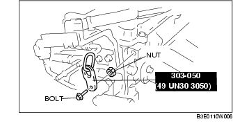
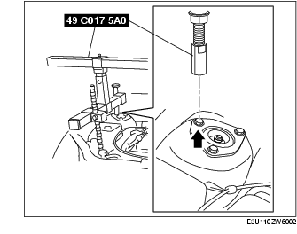
6. Using the bolts part number 99794 1025 or M10×1.25, length 25 mm {0.98 in} to install the SST to the position shown in the figure.
Tightening torque
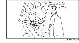
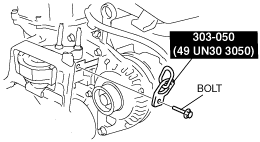
7. To install the front shaft (RH) of the SST (49 C017 5A0), remove the clip shown the figure.
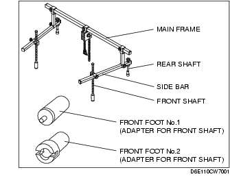
8. Install the SST using the following procedure.
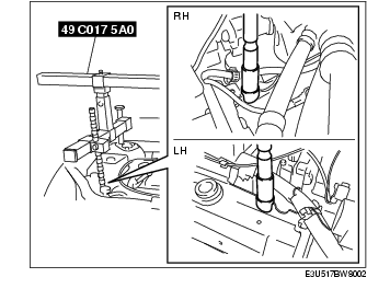
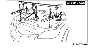
9. Suspend the engine using the SST.
10. Remove the No.3 engine mount.
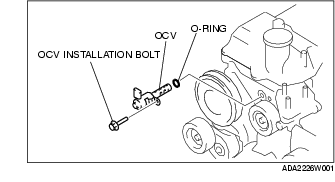
11. Disconnect the OCV connector.
12. Remove the OCV installation bolt.
13. Remove the OCV.
14. Install the new O-ring.
15. Install the OCV.
16. Tighten the OCV installation bolt.
Tightening torque17. Connect the OCV connector.
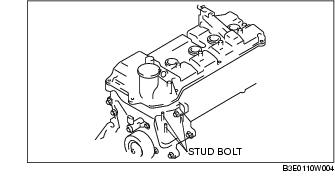
18. Tighten the No.3 engine mount installation stud bolts.
Tightening torque
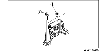
19. Install the No.3 engine mount, and then temporarily tighten the installation bolts and nuts.
20. Tighten the installation bolts and nuts in the order shown in the figure.
Tightening torque
21. Install the clip as shown in the figure.
22. Install the ground. (No.3 engine mount)
23. Install the accelerator cable and bracket.
24. Install the air cleaner component. (See INTAKE-AIR SYSTEM REMOVAL/INSTALLATION [ZY, Z6].)
25. Connect the negative battery cable.
26. Install the battery cover.