 |
am3zzw00009355
CAMSHAFT POSITION (CMP) SENSOR INSPECTION [ZY, Z6]
id0140a0801400
Visual inspection
1. Remove the CMP sensor. (See CAMSHAFT POSITION (CMP) SENSOR REMOVAL/INSTALLATION [ZY, Z6].)
2. Verify that there are no metal shavings on the sensor.
3. Install the CMP sensor. (See CAMSHAFT POSITION (CMP) SENSOR REMOVAL/INSTALLATION [ZY, Z6].)
Voltage inspection
1. Idle the engine.
2. Measure the output voltage using a oscilloscope.
am3zzw00009355
|
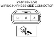
CMP sensor voltage
|
Terminal |
Voltage (V) |
Condition |
|---|---|---|
|
A
|
B+
|
Under any condition
|
|
B
|
4.8 or more
|
High output*
|
|
0.8 or less
|
Low output*
|
|
|
C
|
0
|
Under any condition
|
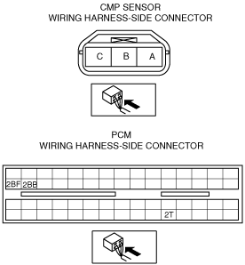
Circuit Open/Short Inspection
1. Remove the PCM connector cover.
2. Disconnect the PCM connector. (See INTAKE-AIR SYSTEM REMOVAL/INSTALLATION [ZY, Z6].)
3. Inspect the following wiring harness for open or short circuit (continuity check).
am3zzw00009356
|
Open circuit
Short circuit