|
am3zzw00009345
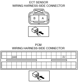
ENGINE COOLANT TEMPERATURE (ECT) SENSOR INSPECTION [ZY, Z6]
id0140a0802000
Continuity Inspection
1. Disconnect the ECT sensor connector.
2. Remove the ECT sensor. (See ENGINE COOLANT TEMPERATURE (ECT) SENSOR REMOVAL/INSTALLATION [ZY, Z6].)
3. Place the ECT sensor in the water and while increasing water temperature, measure the resistance between terminals A and B.
ECT sensor resistance
|
Water temperature (°C {°F}) |
Resistance (kilohm) |
|---|---|
|
20 {68}
|
2.21—2.69
|
|
80 {176}
|
0.287—0.349
|
ECT sensor characteristics graph (reference)
am3zzw00009345
|
Circuit Open/Short Inspection
1. Remove the PCM connector cover.
2. Disconnect the PCM connector. (See INTAKE-AIR SYSTEM REMOVAL/INSTALLATION [ZY, Z6].)
3. Inspect the following wiring harness for open or short circuit (continuity check).
am3zzw00009346
|
Open circuit
Short circuit