FRONT HEATED OXYGEN SENSOR (HO2S) INSPECTION [ZY, Z6]


id0140a0804700

Note
•  Before performing the following inspection, make sure to follow the procedure as indicated in the troubleshooting flowchart. (See HOW TO USE THIS MANUAL.)

Front Heated Oxygen Sensor (HO2S) Voltage Inspection

1.  Warm up the engine to normal operating temperature.

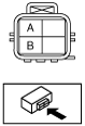
2.  Disconnect the front HO2S connector.

3.  Connect the positive probe of the tester (digital type) to front HO2S terminal A, and the negative probe to front HO2S terminal B and measure the voltage.

am3zzw00009357

4.  Maintain the engine speed at 3,000 rpm until the voltage indicates approx. 0.5—0.7 V.

5.  Verify that the voltage is as indicated in the table when the engine is raced repeatedly.

•  If it cannot be verified, replace the front HO2S. (See FRONT HEATED OXYGEN SENSOR (HO2S) REMOVAL/INSTALLATION [ZY, Z6].)
•  If the monitor item condition/specification (reference) is not within the specification, even though there is no malfunction, perform the “Circuit Open/Short Inspection”.

Front HO2S Voltage Inspection

Engine condition

Voltage (V)

Accelerated
0.5—1.0
Decelerated
0—0.5


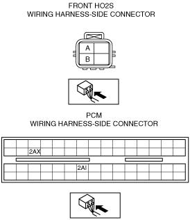
Front Heated Oxygen Sensor (HO2S) Circuit Open/Short Inspection

1.  Remove the PCM connector cover.

2.  Disconnect the PCM connector. (See INTAKE-AIR SYSTEM REMOVAL/INSTALLATION [ZY, Z6].)

3.  Inspect the following wiring harness for open or short circuit (continuity check).

am3zzw00009358


Open circuit

•  If there is no continuity, there is an open circuit. Repair or replace the wiring harness.
―  Front HO2S terminal A and PCM terminal 2AI
―  Front HO2S terminal B and PCM terminal 2AX


Short circuit

•  If there is continuity, there is a short circuit. Repair or replace the wiring harness.
―  Front HO2S terminal A and power supply
―  Front HO2S terminal A and body GND
―  Front HO2S terminal B and power supply
―  Front HO2S terminal B and body GND


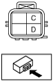
Front Heated Oxygen Sensor (HO2S) Heater Resistance Inspection

1.  Disconnect the front HO2S connector.

2.  Measure the resistance between front HO2S terminals C and D.

am3zzw00009359

•  If not within the specification, replace the front HO2S. (See FRONT HEATED OXYGEN SENSOR (HO2S) REMOVAL/INSTALLATION [ZY, Z6].)
•  If the monitor item condition/specification (reference) is not within the specification, even though there is no malfunction, perform the “Circuit Open/Short Inspection”.
Front HO2S heater resistance
5.0—6.8 ohms [20 °C {68 °F}]


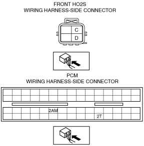
Front Heated Oxygen Sensor (HO2S) Heater Circuit Open/Short Inspection

1.  Remove the PCM connector cover.

2.  Disconnect the PCM connector. (See INTAKE-AIR SYSTEM REMOVAL/INSTALLATION [ZY, Z6].)

3.  Inspect the following wiring harness for open or short circuit (continuity check).

am3zzw00009360


Open circuit

•  If there is no continuity, there is an open circuit. Repair or replace the wiring harness.
―  Front HO2S terminal C and PCM terminal 2T
―  Front HO2S terminal D and PCM terminal 2AM


Short circuit

•  If there is continuity, there is a short circuit. Repair or replace the wiring harness.
―  Front HO2S terminal C and body GND
―  Front HO2S terminal D and power supply
―  Front HO2S terminal D and body GND