 |
am3zzw00009627
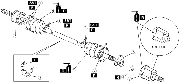
DRIVE SHAFT (TRIPOD JOINT) DISASSEMBLY/ASSEMBLY
id031300801700
1. Disassemble in the order indicated in the table.
2. Assemble in the reverse order of disassembly.
am3zzw00009627
|
|
1
|
Boot band (wheel side, transaxle side: smaller diameter)
|
|
2
|
Boot band (transaxle side larger diameter)
|
|
3
|
Outer ring
(See Outer Ring Disassembly Note.)
(See Outer Ring Assembly Note.)
|
|
4
|
Snap ring
|
|
5
|
Tripod joint
|
|
6
|
Boot
(See Boot Disassembly Note.)
(See Boot Assembly Note.)
|
|
7
|
Dynamic damper (ZY, Z6, LF and L3 (MTX/LH), LF and L3 (ATX/RH))
(See Dynamic Damper Assembly Note.)
|
|
8
|
Shaft and ball joint component
|
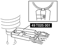
Boot Band (Wheel Side, Transaxle Side: Smaller Diameter) Disassembly Note
1. Remove the boot band using end clamp pliers.
am3zzw00009628
|
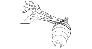
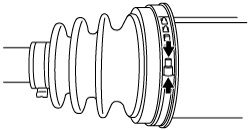
Boot Band (Transaxle Side Larger Diameter) Disassembly Note
1. Pry up the boot band at the points indicated in the figure using pliers and remove the band.
am3zzw00009629
|
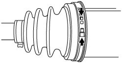
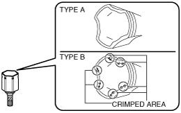
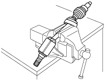
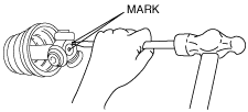
Outer Ring Disassembly Note
am3zzw00009630
|
Type A
1. Place an alignment mark on the drive shaft and outer ring.
am3zzw00009631
|
2. Remove the outer ring.
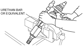
Type B
1. Place an alignment mark on the drive shaft and outer ring.
am3zzw00009631
|
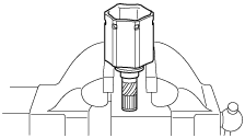
2. Secure the drive shaft using a vise.
am5ezw00000034
|
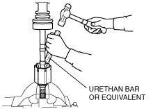
3. Tap the outer ring slightly by using a hummer and urethan bar or equivalent, and remove the outer ring from the drive shaft.
am5ezw00000035
|
Snap Ring, Tripod Joint Disassembly Note
1. Place an alignment mark on the shaft and tripod joint.
2. Remove the snap ring using snap ring pliers.
am3zzw00009632
|
3. Remove the tripod joint from the shaft.
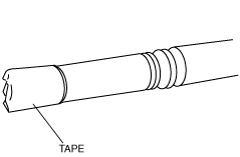
Boot Disassembly Note
1. Wrap the shaft splines with tape.
am3zzw00009633
|
2. Remove the boot.
Boot Assembly Note
1. Fill the inside of the new dust boot (wheel side) with grease.
Grease amount
|
|
LH |
RH |
|---|---|---|
|
ZY (ATX)
|
93—103 g {3.29—3.63 oz}
|
93—103 g {3.29—3.63 oz}
|
|
ZY (MTX)
|
93—103 g {3.29—3.63 oz}
|
—
|
|
Z6 (ATX)
|
93—103 g {3.29—3.63 oz}
|
93—103 g {3.29—3.63 oz}
|
|
Z6 (MTX)
|
93—103 g {3.29—3.63 oz}
|
—
|
|
LF (ATX)
|
93—103 g {3.29—3.63 oz}
|
93—103 g {3.29—3.63 oz}
|
|
LF (MTX)
|
110—120 g {3.89—4.23 oz}
|
—
|
|
L3 (ATX)
|
110—120 g {3.89—4.23 oz}
|
110—120 g {3.89—4.23 oz}
|
|
L3 (MTX)
|
110—120 g {3.89—4.23 oz}
|
—
|
2. Install the boot with the drive shaft spline still wrapped with vinyl tape.
3. Remove the vinyl tape.
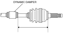
Dynamic Damper Assembly Note
1. Install the dynamic damper as shown in the figure.
am3zzw00009634
|
2. Install a new boot band onto the dynamic damper.
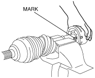
Tripod Joint, Snap Ring Assembly Note
1. While aligning the marks on the shaft and the tripod joint, insert the tripod joint using a bar and a hammer.
am3zzw00009635
|
2. Insert a new snap ring using snap ring pliers.
Outer Ring Assembly Note
am3zzw00009630
|
1. Fill the outer ring and boot (transaxle side) with the specified grease.
Grease amount
|
|
LH |
RH |
|---|---|---|
|
ZY (ATX)
|
127—141 g {4.49—4.97 oz}
|
127—141 g {4.49—4.97 oz}
|
|
ZY (MTX)
|
127—141 g {4.49—4.97 oz}
|
—
|
|
Z6 (ATX)
|
127—141 g {4.49—4.97 oz}
|
127—141 g {4.49—4.97 oz}
|
|
Z6 (MTX)
|
127—141 g {4.49—4.97 oz}
|
—
|
|
LF (ATX)
|
109—123 g {3.85—4.34 oz}
|
109—123 g {3.85—4.34 oz}
|
|
LF (MTX)
|
153—167 g {5.41—5.89 oz}
|
—
|
|
L3 (ATX)
|
115—129 g {4.06—4.55 oz}
|
115—129 g {4.06—4.55 oz}
|
|
L3 (MTX)
|
153—167 g {5.41—5.89 oz}
|
—
|
2. Assemble the outer ring. [Type A]
3. Perform the following servicing to assemble the outer ring. [Type B]
am5ezw00000039
|
am5ezw00000040
|
4. Set the drive shaft to the standard length.
Lockbolt type
|
|
LH |
RH |
|---|---|---|
|
ZY (MTX)
|
629.2—639.2 mm {24.78—25.16 in}
|
—
|
|
ZY (ATX)
|
598.5—608.5 mm {23.57—23.95 in}
|
526.8—536.8 mm {20.75—21.13 in}
|
|
Z6 (MTX)
|
629.2—639.2 mm {24.78—25.16 in}
|
—
|
|
Z6 (ATX)
|
598.5—608.5 mm {23.57—23.95 in}
|
526.8—536.8 mm {20.75—21.13 in}
|
|
LF (MTX)
|
611.7—621.7 mm {24.08—24.47 in}
|
—
|
|
LF (ATX)
|
599.5—609.5 mm {23.61—23.99 in}
|
527.9—537.9 mm {20.79—21.17 in}
|
|
L3 (MTX)
|
611.7—621.7 mm {24.08—24.47 in}
|
—
|
|
L3 (ATX)
|
599.5—609.5 mm {23.61—23.99 in}
|
527.9—537.9 mm {20.79—21.17 in}
|
Locknut type
|
|
LH |
RH |
|---|---|---|
|
ZY (MTX)
|
650.9—657.9 mm {25.63—25.90 in}
|
—
|
|
ZY (ATX)
|
621.4—628.4 mm {24.47—24.74 in}
|
549.2—556.2 mm {21.63—21.89 in}
|
|
Z6 (MTX)
|
650.9—657.9 mm {25.63—25.90 in}
|
—
|
|
Z6 (ATX)
|
621.4—628.4 mm {24.47—24.74 in}
|
549.2—556.2 mm {21.63—21.89 in}
|
|
LF (MTX)
|
641.5—649.5 mm {25.26—25.57 in}
|
—
|
|
LF (ATX)
|
623.9—631.9 mm {24.57—24.87 in}
|
553.1—561.1 mm {21.78—22.09 in}
|
|
L3 (MTX)
|
641.5—649.5 mm {25.26—25.57 in}
|
—
|
|
L3 (ATX)
|
624.7—632.7 mm {24.60—24.90 in}
|
555.3—563.3 mm {21.87—22.17 in}
|
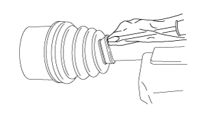
5. Release any trapped air from the boots by carefully lifting up the small end of each boot with a cloth wrapped screwdriver.
am3zzw00009636
|
6. Verify that the drive shaft length is within the specification under atmospheric pressure inside the boot.
Boot Band (Transaxle Side Larger Diameter) Assembly Note
1. Pry up the boot band at the points indicated in the figure using pliers and tighten the boot band.
am3zzw00009637
|
Boot Band (Wheel Side, Transaxle Side Smaller Diameter) Assembly Note
1. Adjust opening width A by turning the adjusting bolt of the SST.
am3zzw00009638
|
2. Crimp the wheel side small boot band completely closed so there is no gap using the SST.
am3zzw00009639
|
3. Verify that the boot band does not protrude from the boot band installation area.
4. Fill the boot with the repair kit grease.
5. Adjust opening width A of the SST to the specification.
6. Crimp the wheel side large boot band completely closed so there is no gap using the SST.
7. Verify that the boot band does not protrude from the boot band installation area.