Diagnostic procedure
|
STEP
|
INSPECTION
|
ACTION
|
|
|---|---|---|---|
|
1
|
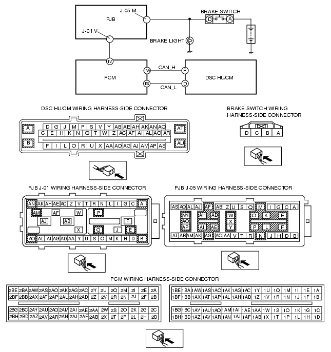
VERIFY OPEN OR SHORT CIRCUIT IN BRAKE SWITCH SIGNAL
• Turn the ignition switch to the ON position.
• Measure the voltage between the following PCM terminals and body ground when the brake pedal is depressed and released:
Voltage Brake pedal depressed: B+ Brake pedal released: 1 V or less |
Yes
|
Go to Step 5.
|
|
No
|
If it is B+ under any condition, then go to the next step.
If it is 1 V or less under any condition, then go to Step 3.
|
||
|
2
|
INSPECT BRAKE SWITCH SIGNAL FOR SHORT TO POWER SUPPLY CIRCUIT
• Disconnect the brake switch connector.
• Measure the voltage between the brake switch connector terminal D (vehicle harness-side) and body ground.
• Is the voltage 1 V or less?
|
Yes
|
Go to Step 4.
|
|
No
|
Repair or replace the wiring harness between the PCM and brake switch, then go to Step 5.
|
||
|
3
|
INSPECT BRAKE SWITCH SIGNAL FOR OPEN CIRCUIT
• Disconnect the PCM connectors.
• Disconnect the brake switch connector.
• Inspect continuity between the following PCM connector terminals (vehicle harness-side) and brake switch terminal D:
• Is there continuity?
|
Yes
|
Go to the next step.
|
|
No
|
Repair or replace the wiring harness between the PCM and brake switch, then go to Step 5.
|
||
|
4
|
INSPECT BRAKE SWITCH
• Inspect the brake switch.
(See BRAKE SWITCH INSPECTION.)
• Is the brake switch normal?
|
Yes
|
Go to the next step.
|
|
No
|
Replace the brake switch, then go to the next step.
|
||
|
5
|
VERIFY THAT THE SAME DTC IS NOT PRESENT
• Reconnect all disconnected connectors.
• Clear the DTCs from the memory.
(See Clearing DTCs Procedures.)
• Start the engine and drive the vehicle at 20 km/h {12.4 mph} or more.
• Are the same DTCs present?
|
Yes
|
Repeat the inspection from Step 1.
If the malfunction recurs, replace the DSC CM, then go to the next step.
|
|
No
|
Go to the next step.
|
||
|
6
|
VERIFY THAT NO OTHER DTCS ARE PRESENT
• Are any other DTCs output?
|
Yes
|
Go to the applicable DTC inspection.
(See DTC Table.)
|
|
No
|
DTC troubleshooting completed.
|
||