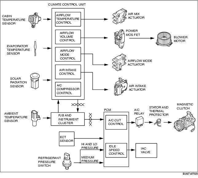
FULL-AUTO AIR CONDITIONER FUNCTION


id074000100600

Block Diagram

• The control system consists of input components (sensors), output components (actuators, magnetic clutch, power MOS FET, and other parts), and a control device (climate control unit).

Control Table

• The full-auto air conditioner system functions based on the five basic types of controls and three supplementary functions.

Basic control

Control description

Correction control

Airflow temperature control
Airflow temperature automatic control
• Air intake correction
• A/C correction
• MAX HOT and MAX COLD correction
• Engine coolant temperature correction
Airflow volume control
Airflow volume automatic control
• Engine coolant temperature correction (warm-up correction)
• Vehicle speed correction
• Mild start correction
• MAX HOT and MAX COLD correction
• Window fogging prevention correction at start
• Starting compensation correction
• Defroster correction
• Starting burnt-out prevention function
Airflow volume manual control
• Defroster correction
• Starting burnt-out prevention function
Airflow mode control
Airflow mode automatic control
• Engine coolant temperature correction (warm-up correction)
Airflow mode manual control
-
Air intake control
Air intake automatic control
• MAX COLD correction
• Defroster correction
• Ambient temperature correction
• A/C OFF correction
Air intake manual control
• Defroster correction
A/C compressor control
A/C compressor automatic control
• Defroster correction
• Ambient temperature correction
• MAX COLD correction
• Wiper correction
• Window fogging prevention correction at start
A/C compressor manual control
• Defroster correction
• Ambient temperature correction
• Window fogging prevention correction at start

Supplementary function

Fail-safe function
Sensor signal delay function
On-board diagnostic function

Control Type Transition by Switch Operation

Airflow temperature control, airflow volume control

Operation switch

Airflow temperature control

Airflow volume control

Control prior to switch operation

Control prior to switch operation

Automatic control

Automatic control

Defroster correction

Manual control

OFF

1

2

3

4

5

6

7

OFF switch
Automatic control
OFF
OFF
OFF
AUTO switch
Automatic control
Automatic control
Automatic control
Automatic control
Fan switch
+
Automatic control
Manual control*2
Manual control*2
1
2
3
4
5
6
7
7
-
Automatic control
Manual control*3
Manual control*3
1
1
1
2
3
4
5
6
VENT switch
Automatic control
Automatic control

*5

No change
BI-LEVEL switch
Automatic control
Automatic control

*5

No change
HEAT switch
Automatic control
Automatic control

*5

No change
HEAT/DEF switch
Automatic control
Automatic control

*5

No change
DEFROSTER switch
Automatic control
Defroster correction
No change
Defroster correction
A/C switch
Automatic control
Automatic control
No change
No change
REC/FRESH switch
Automatic control
Automatic control
No change
No change
Temperature setting dial*1
18.0
MAX COLD
MAX HI
MAX HI
No change
18.5-31.5
Automatic control
Automatic control
No change
No change
32.0
MAX HOT
AUTO HI*4
AUTO HI
No change

*1 :
Adjusted up or down in increments of 0.5 within a range of 18.0-32.0. When the fan is OFF, the temperature setting can be adjusted in increments of ±1.0.
*2 :
Increases to the manual voltage that is closest to the auto or defroster correction voltage.
*3 :
Decreases to the manual voltage that is closest to the auto or defroster correction voltage.
*4 :
Engine coolant temperature correction takes precedence.
*5 :
Returns to condition prior to defroster operation. However, if it had been off prior to defroster operation, it switches to automatic control.

Airflow mode control, air intake control, A/C compressor control

Operation switch

Airflow mode control

Air intake control

A/C compressor control

Control prior to switch operation

Control prior to switch operation

Control prior to switch operation

Automatic control

Manual control

Automatic control

Manual control

Automatic control

Manual control

OFF switch
Fixed at mode before turned OFF*2
No change*2
Fixed at mode before turned OFF*2
No change*2
OFF
OFF
AUTO switch
Automatic control
Automatic control
Automatic control
Automatic control
Automatic control
Automatic control
Fan switch
+
Automatic control
No change
Automatic control
No change
Automatic control
No change
-
Automatic control
No change
Automatic control
No change
Automatic control
No change
VENT switch
No change*2
No change*2
Automatic control
No change*2
Automatic control
DEFROSTER*3
BI-LEVEL switch
No change*2
No change*2
Automatic control
No change*2
Automatic control
DEFROSTER*3
HEAT switch
No change*2
No change*2
Automatic control
No change*2
Automatic control
DEFROSTER*3
HEAT/DEF switch
No change*2
No change*2
Automatic control
No change*2
Automatic control
DEFROSTER*3
DEFROSTER switch
DEFROSTER
DEFROSTER
Defroster correction
A/C switch
Automatic control
No change
Automatic control
No change
A/C→OFF
OFF→A/C*4
A/C→OFF
OFF→A/C*4
REC/FRESH switch
Automatic control
No change
FRESH→REC
REC→FRESH
 
FRESH→REC
REC→FRESH
Automatic control
No change
Temperature setting dial*1
18.0
Automatic control
No change
Automatic control
No change
Automatic control
No change
18.5-31.5
Automatic control
No change
Automatic control
No change
Automatic control
No change
32.0
Automatic control
No change
Automatic control
No change
Automatic control
No change

*1 :
Adjusted up or down in increments of 0.5 within a range of 18.0-32.0. When the fan is OFF, the temperature setting can be adjusted in increments of ±1.0.
*2 :
If operated during defroster correction, it returns to the condition prior to defroster operation.
*3 :
If operated during defroster correction, it returns to the condition prior to defroster operation. However, if it had been off prior to defroster operation, it switches to automatic control.
*4 :
When the fan is OFF, it is fixed at A/C OFF.