|
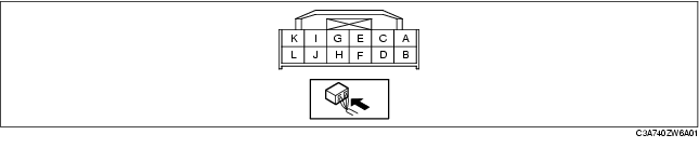
Terminal
|
Signal name
|
Connected to
|
Measurement condition
|
Voltage (V)
|
Inspection item (s)
|
|
A
|
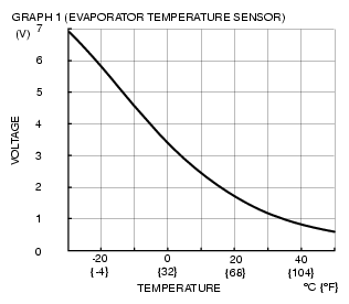
Evaporator temperature sensor input
|
Evaporator temperature sensor
|
Compared with temperature detected by evaporator temperature sensor
|
Refer to graph 1
|
• Wiring harness: continuity (Climate control unit-evaporator temperature sensor: A-B, B-A)
• Wiring harness: short circuit (Climate control unit-evaporator temperature sensor: A-B)
• Evaporator temperature sensor
• Climate control unit: terminal voltage (E, K)
|
|
B
|
Sensor GND
|
Evaporator temperature sensor
|
Under any condition
|
1.0 or less
|
• Climate control unit: terminal voltage (E)
|
|
C
|
A/C
|
PJB
|
A/C switch on, fan switch at 1st
|
1.0 or less
|
• Wiring harness: continuity (Climate control unit-PJB: C-J-04 AF)
|
|
A/C switch off
|
B+
|
• Wiring harness: continuity, short circuit (Climate control unit-PJB: C-J-04 AF)
• PJB
|
|
D
|
TNS signal
|
PJB
|
Light switch at TNS position
|
Panel light control switch turned to the brightest setting
|
1.0 or less
|
• Wiring harness: short circuit (Climate control unit-PJB: D-J-03 AI)
• PJB
• Panel light control switch
|
|
Panel light control switch turned to the darkest setting
|
|
|
Light switch at OFF position
|
1.0 or less
|
• Wiring harness: continuity, short circuit (Climate control unit-PJB: D-J-03 AI)
• PJB
• Climate control unit: terminal voltage (J)
|
|
E
|
GND
|
Body ground
|
Under any condition
|
1.0 or less
|
• Wiring harness: continuity (Climate control unit-GND: E-GND)
|
|
F
|
FAN signal
|
Fan switch
|
FAN switch on
|
1.0 or less
|
• Wiring harness: continuity (Climate control unit-fan switch: F-A)
• Fan switch
|
|
FAN switch off
|
0
|
• Wiring harness: continuity (Climate control unit-fan switch: F-A)
• Climate control unit: terminal voltage (K)
• Fan switch
|
|
G
|
Rear window defroster switch indicator light
|
PJB
|
Rear window defroster switch on
|
1.0 or less
|
• Wiring harness: continuity (Climate control unit-PJB: G-J-04 I)
• PJB
|
|
Rear window defroster switch off
|
5.0 or less
|
• Wiring harness: short circuit (Climate control unit-PJB: G-J-04 I)
• PJB
|
|
H
|
-
|
-
|
-
|
-
|
-
|
|
I
|
Rear window defroster switch
|
PJB
|
Rear window defroster switch is pressed
|
1.0 or less
|
• Climate control unit: terminal voltage (E)
|
|
Rear window defroster switch is released
|
B+
|
• Wiring harness: open circuit, short circuit (Climate control unit-PJB: R-J-04 AD)
• PJB
|
|
J
|
TNS signal
|
PJB (TNS relay)
|
Light switch at TNS position
|
B+
|
• Wiring harness: short circuit (Climate control unit-PJB: J-J-03H)
• PJB
|
|
Light switch at OFF position
|
1.0 or less
|
• Wiring harness: continuity (Climate control unit-PJB: J-J-03H)
• PJB
|
|
K
|
IG2
|
A/C 10 A fuse
|
Ignition switch at ON
|
B+
|
• Wiring harness: continuity, short circuit (Climate control unit- PJB: K-J-03AD)
• A/C 10 A fuse
• PJB
|
|
Ignition switch at LOCK
|
1.0 or less
|
• Wiring harness: continuity, short circuit (Climate control unit- PJB: K-J-03AD)
• PJB
|
|
L
|
B+
|
ROOM 15 A fuse
|
Under any condition
|
B+
|
• Wiring harness: continuity, short circuit (Climate control unit- PJB: L-J-03R)
• PJB
• ROOM 15 A fuse
|