|
STEP
|
INSPECTION
|
ACTION
|
|
1
|
INSPECT PJB POWER SUPPLY FUSES
• Are the PJB power supply fuses normal?
|
Yes
|
Go to the next step.
|
|
No
|
Install an appropriate amperage fuse.
|
|
2
|
INSPECT DOOR LATCH SWITCH INSTALLATION
• Are the door latch switches installed securely?
|
Yes
|
Go to the next step.
|
|
No
|
Install the door latch switches securely, then go back to Step 5 of KEYLESS ENTRY SYSTEM PRELIMINARY INSPECTION.
|
|
*3
|
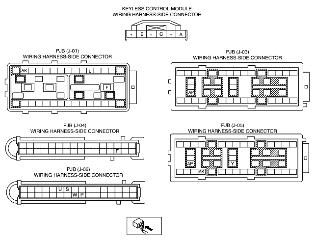
INSPECT IF MALFUNCTION IS IN WIRING HARNESS (NO CONTINUITY BETWEEN FUSE BLOCK AND PJB) OR ELSEWHERE
• Turn the ignition switch to the ON position.
• Measure the voltage at the following PJB terminals:
-
- IG1 signal (terminal J-03 AP)
-
- Power supply signal (terminal J-01 F)
• Is the voltage B+?
|
Yes
|
Go to the next step.
|
|
No
|
Repair the wiring harness between the fuse block and PJB, then go to Step 13.
|
|
*4
|
INSPECT IF MALFUNCTION IS IN WIRING HARNESS (SHORT TO POWER SUPPLY BETWEEN FUSE BLOCK AND PJB, OR BETWEEN PJB AND GROUND) OR ELSEWHERE
• Turn the ignition switch to the LOCK position.
• Disconnect the PJB connector.
• Measure the voltage at the following PJB terminal (wiring harness-side):
-
- IG1 signal (terminal J-03 AP)
• Is the voltage B+?
|
Yes
|
Repair the malfunctioning wiring harness, then go to Step 13.
|
|
No
|
Go to the next step.
|
|
*5
|
INSPECT IF MALFUNCTION IS IN WIRING HARNESS (NO CONTINUITY BETWEEN PJB AND GROUND) OR ELSEWHERE
• Is there continuity between PJB terminal J-03 C, J-03 X and ground?
|
Yes
|
Go to the next step.
|
|
No
|
Repair the wiring harness between the PJB and ground, then go to Step 13.
|
|
6
|
INSPECT FOR CHECK CODE 04 IN INSTRUMENT CLUSTER
• Inspect the door latch switch using the instrument cluster input/output check mode.
• Is DTC 04 displayed?
|
Yes
|
Go to the next step.
|
|
No
|
Repair the door latch switch system using the DTC 04 inspection procedure, then go to Step 13.
|
|
7
|
INSPECT PJB OR WIRING HARNESS (BETWEEN PJB AND DOOR LATCH SWITCHES FOR CONTINUITY)
• Open all doors.
• Is there continuity between PJB terminals J-06 P, J-06 S, J-06 U, J-06 W and ground?
|
Yes
|
Replace the PJB and reprogram the transmitter ID code, then go to the next step.
|
|
No
|
Repair the wiring harness between the PJB and door latch switches, then go to the next step.
|
|
8
|
INSPECT POWER SUPPLY FUSE
• Is the keyless control module power supply fuse normal?
|
Yes
|
Go to the next step.
|
|
No
|
Install an appropriate amperage fuse.
|
|
9
|
INSPECT IF MALFUNCTION IS IN WIRING HARNESS (NO CONTINUITY BETWEEN FUSE BLOCK AND KEYLESS CONTROL MODULE) OR ELSEWHERE
• Turn the ignition switch to the ON position.
• Measure the voltage at the following keyless control module terminal:
-
- IG1 signal (terminal A)
• Is the voltage B+?
|
Yes
|
Go to the next step.
|
|
No
|
Repair the wiring harness between the fuse block and keyless control module, then go to Step 13.
|
|
10
|
INSPECT IF MALFUNCTION IS IN WIRING HARNESS (NO CONTINUITY BETWEEN KEYLESS CONTROL MODULE AND GROUND) OR ELSEWHERE
• Is there continuity between keyless control module terminal E and ground?
|
Yes
|
Go to the next step.
|
|
No
|
Repair the wiring harness between the keyless control module and ground, then go to Step 13.
|
|
11
|
INSPECT IF MALFUNCTION IS IN WIRING HARNESS (NO CONTINUITY BETWEEN KEYLESS CONTROL MODULE AND PJB) OR ELSEWHERE
• Turn the ignition switch to the ON position.
• Disconnect the keyless control module connector and PJB connector.
• Is there continuity between the following terminals?
-
- J-04 F (PJB connector)-C (keyless control module connector)
|
Yes
|
Go to the next step.
|
|
No
|
Repair the wiring harness between the keyless control module and PJB, then go to Step 13.
|
|
12
|
INSPECT IF MALFUNCTION IS IN WIRING HARNESS (NO CONTINUITY BETWEEN KEYLESS CONTROL MODULE AND PJB) OR PJB
• Measure the voltage at keyless control module terminal C.
-
- When transmitter operated:
-
• Any transmitter button is operated without key in steering lock (key reminder switch off): 5 V → 1.0 V or less
-
• Key is in steering lock (key reminder switch on): 0.5 V or less
• Is the voltage normal?
|
Yes
|
Replace the PJB, then go to the next step.
|
|
No
|
Replace the keyless control module, then go to the next step.
|
|
13
|
REINSPECT MALFUNCTION SYMPTOM AFTER REPAIR
• Does the keyless entry system operate properly?
|
Yes
|
Troubleshooting completed.
Explain repairs to the customer.
|
|
No
|
Reinspect the malfunction symptoms, then repeat from Step 1 if the malfunction recurs.
|