• Refer to Mazda3 Workshop Manual.
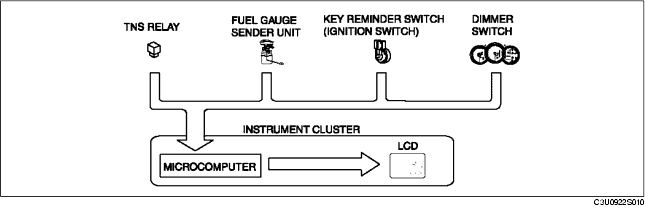
• When the parts listed in the chart are operated and signal is output to the instrument cluster, the built-in microcomputer determines the operability of the input circuit based on that signal.
|
Check code
|
Parts sending input signal
|
|---|---|
|
08
|
TNS relay
|
|
22
|
Fuel gauge sender unit
|
|
31
|
Key reminder switch (built into the ignition switch)
|
|
55
|
Dimmer switch (built into the instrument cluster)
|
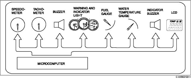
• By operating the parts listed in the chart, the built-in microcomputer determines the operability of the individual parts.
• The PID/data monitoring items for the instrument cluster is as shown in following the table:
Monitor item table