1. Inspect the speedometer by setting it to check code 12 of the input/output check mode. (See INSTRUMENT CLUSTER INPUT/OUTPUT CHECK MODE.)
1. Adjust the tire pressure to the specification.
2. Using a speedometer tester, verify that the tester reading is as indicated in the table below.
|
Speedometer tester indication (km/h)
|
Allowable range (km/h)
|
|---|---|
|
20
|
20-24
|
|
40
|
40-44
|
|
60
|
60-65
|
|
80
|
80-86
|
|
100
|
101-106
|
|
120
|
121-127
|
|
140
|
141-148
|
1. Inspect the tachometer by setting it to check code 13 of the input/output check mode. (See INSTRUMENT CLUSTER INPUT/OUTPUT CHECK MODE.)
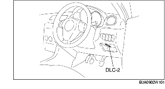
1. Connect the WDS or equivalent to the diagnostic connector 2 (16-pin).
2. Compare the data monitor item (RPM) with the tachometer indication.
1. Inspect the fuel gauge by setting it to check code 23 of the input/output check mode. (See INSTRUMENT CLUSTER INPUT/OUTPUT CHECK MODE.)
1. Inspect the water temperature gauge by setting it to check code 25 of the input/output check mode. (See INSTRUMENT CLUSTER INPUT/OUTPUT CHECK MODE.)