|
belbze00000186
CYLINDER BLOCK DISASSEMBLY (II)
id011000500700
1. Disassemble in the order indicated in the table.
belbze00000186
|
|
1
|
Pilot bearing (If equipped)
|
|
2
|
Balancer unit (L3, L5)
|
|
3
|
Connecting rod cap
|
|
4
|
Lower connecting rod bearing
|
|
5
|
Connecting rod, piston component
|
|
6
|
Upper connecting rod bearing
|
|
7
|
Piston ring
|
|
8
|
Snap ring (Full floating type piston pin)
|
|
9
|
Piston pin (Full floating type piston pin)
|
|
10
|
Piston (Full floating type piston pin)
|
|
11
|
Connecting rod (Full floating type piston pin)
|
|
12
|
Main bearing cap
|
|
13
|
Lower main bearing
|
|
14
|
Crankshaft
|
|
15
|
Upper main bearing, thrust bearing
|
|
16
|
Oil jet valve
|
|
17
|
Cylinder block
|
|
18
|
Adjustment shim (L3, L5)
|
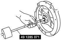
Pilot Bearing Disassembly Note
1. Use the SST to remove the pilot bearing.
belbze00000053
|
Connecting Rod Cap Disassembly Note
1. Before removing the connecting rod cap, inspect the connecting rod side clearance. (See CONNECTING ROD INSPECTION.)
2. Remove the connecting rod bolt from the connecting rod cap by tapping the bolt with a plastic hammer.
Main Bearing Cap Disassembly Note
1. Before removing the main bearing cap, inspect the crankshaft end play. (See CRANKSHAFT INSPECTION.)
2. Loosen the main bearing cap bolts in two or three steps in the order shown in the figure.
belbze00000054
|