 |
E6U517SI5001
AUTOMATIC TRANSAXLE DISASSEMBLY
d6e051700000a02
Precaution
General notes
Disassembly
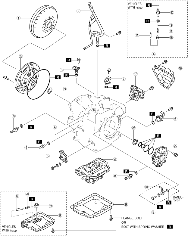
Components
E6U517SI5001
|
|
1
|
Torque converter
|
|
2
|
Oil filler tube and oil dipstick
|
|
3
|
Input/turbine speed sensor
|
|
4
|
Oil pressure switch
|
|
5
|
Transaxle range switch
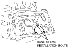
|
|
6
|
Vehicle speed sensor
|
|
7
|
Intermediate sensor
|
|
8
|
Connector pipe
|
|
9
|
Connector bolt
|
|
10
|
Oil pipe
|
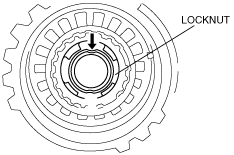
|
11
|
Stud bolt
|
|
12
|
Connector bolt
|
|
13
|
Steel ball
|
|
14
|
Spring
|
|
15
|
Plug
|
|
16
|
Oil cover
|
|
17
|
Secondary control valve body
|
|
18
|
Oil pan
|
|
19
|
Hose
|
|
20
|
Joint pipe
|
|
21
|
Joint
|
|
22
|
Primary control valve body
|
|
23
|
Oil pump
|
|
24
|
Thrust washer
|
|
25
|
End cover
|
|
26
|
Bearing race
|
d6e517za5109
|
|
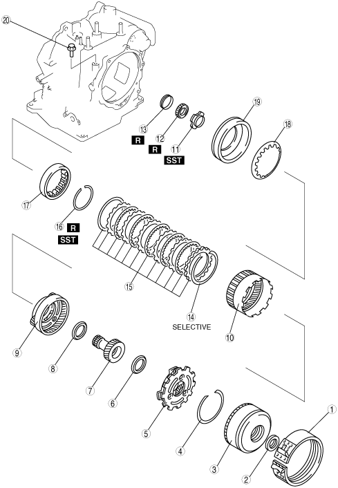
1
|
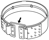
2–4 brake band
|
|
2
|
Needle bearing
|
|
3
|
Clutch component
|
|
4
|
Snap ring
|
|
5
|
Rear planetary gear component
|
|
6
|
Needle bearing
|
|
7
|
Front sun gear
|
|
8
|
Needle bearing
|
|
9
|
Front planetary gear component
|
|
10
|
Front internal gear and one-way clutch
|
|
11
|
Lock nut
|
|
12
|
Bearing
|
|
13
|
Distance piece
|
|
14
|
Snap ring
|
|
15
|
Low and reverse brake
|
|
16
|
Snap ring
|
|
17
|
One-way clutch inner race
|
|
18
|
Piston return spring
|
|
19
|
Low and reverse brake piston
|
|
20
|
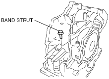
Band strut
|
d6e517za5110
|
|
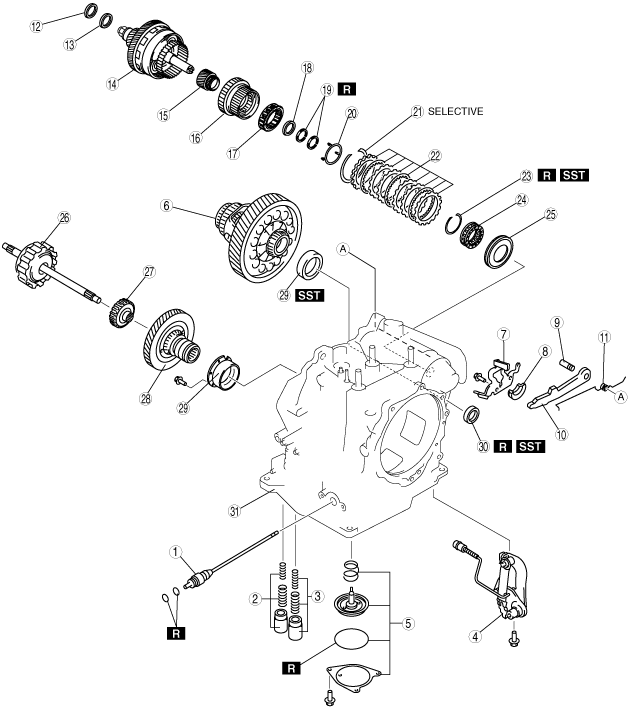
1
|
Manual shaft
|
|
2
|
Servo apply accumulator
|
|
3
|
Forward accumulator
|
|
4
|
Parking rod lever component
|
|
5
|
Band servo
|
|
6
|
Differential
|
|
7
|
Actuator plate
|
|
8
|
Support actuator
|
|
9
|
Parking pawl shaft
|
|
10
|
Parking pawl
|
|
11
|
Pawl return spring
|
|
12
|
Needle bearing
|
|
13
|
Bearing race
|
|
14
|
Output gear component
|
|
15
|
Secondary sun gear
|
|
16
|
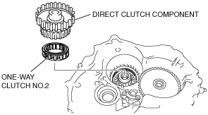
Direct clutch component
|
|
17
|
One-way clutch No.2
|
|
18
|
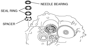
Needle bearing
|
|
19
|
Seal rings
|
|
20
|
Spacer
|
|
21
|
Snap ring
|
|
22
|
Reduction brake
|
|
23
|
Snap ring
|
|
24
|
Springs and retainer component
|
|
25
|
Reduction brake piston
|
|
26
|
Forward clutch
|
|
27
|
Forward clutch hub
|
|
28
|
Primary gear
|
|
29
|
Bearing race
|
|
30
|
Oil seal
|
|
31
|
Transaxle case
|
d6e517za5111
|
|
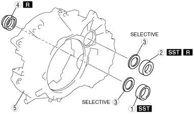
1
|
Bearing race
|
|
2
|
Bearing
|
|
3
|
Adjustment shim
|
|
4
|
Oil seal
|
|
5
|
Converter housing
|
Disassembly procedure
1. Remove the torque converter, and immediately turn it so that the hole faces upward.
This will help to keep any remaining fluid from spilling.
2. Remove the ATF dipstick and oil filler tube.
3. Remove the O-ring from the oil filler tube.
4. Remove the breather hose.
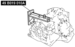
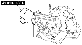
5. Assemble the SST.
d6j517za4130
|
6. Lift the transaxle and mount it on the SST.
d6j517za4131
|
7. Remove the input/turbine speed sensor.
8. Remove the O-ring from the input/turbine speed sensor.
9. Remove the oil pressure switch.
10. Remove the transaxle range switch.
11. Remove the vehicle speed sensor.
12. Remove the O-ring from the vehicle speed sensor.
13. Remove the intermediate sensor.
14. Remove the O-ring from the intermediate sensor.
15. Remove the connector pipe, connector bolt and oil pipe.
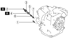
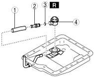
16. Remove in the order shown in the figure. (vehicles with i-stop)
EZE517ZSI002
|
|
1
|
Stud bolt
|
|
2
|
O-ring
|
|
3
|
Connector bolt
|
|
4
|
Packing
|
|
5
|
Steel ball
|
|
6
|
Spring
|
|
7
|
Plug
|
17. Remove the oil cover.
Examine any material found in the pan or on the magnet to determine the condition of the transaxle. If large amounts of material are found, replace the torque converter and carefully inspect the transaxle for the cause.
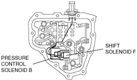
18. Disconnect the solenoid valve connector.
d6e517za5004
|
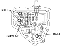
19. Remove the bolts as shown in the figure.
d6e517za5005
|
20. Remove the secondary control valve body.
21. Remove the coupler component.
d6e517za5009
|
22. Remove the O-rings and tubular pins from the transaxle case.
23. Remove the oil pan.
Examine any material found in the pan or on the magnet to determine the condition of the transaxle. If large amounts of material are found, replace the torque converter and carefully inspect the transaxle for the cause.
24. Remove in the order shown in the figure. (vehicles with i-stop)
EZE517ZSI003
|
|
1
|
Hose
|
|
2
|
Joint pipe
|
|
3
|
O-ring
|
|
4
|
Joint
|
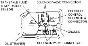
25. Disconnect the solenoid valve connector, ground, and transaxle fluid temperature sensor.
d6e517za5010
|
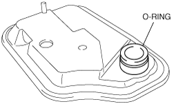
26. Remove the oil strainer.
27. Remove the O-ring from the oil strainer.
d6e517za5099
|
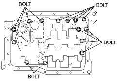
28. Remove the bolts as shown in the figure.
d6e517aw5029
|
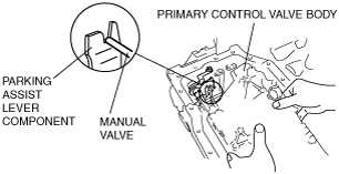
29. Remove the Primary control valve body.
d6e517za5002
|
30. Remove the coupler component.
d6j517za4008
|
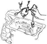
31. Remove the accumulator component.
d6e517za5011
|
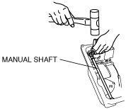
32. Remove the manual shaft.
d6e517za5012
|
d6e517za5013
|
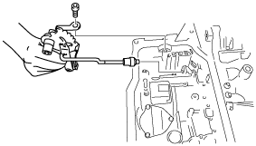
33. Remove the parking rod lever component.
d6j517za4012
|
34. Remove the band servo component.
d6e517za5014
|
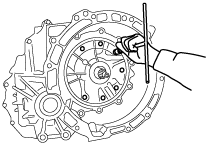
35. Remove the oil pump.
d6j517za4014
|
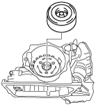
36. Remove the converter housing by tapping lightly with a plastic hammer.
d6j517za4015
|
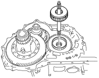
37. Remove the forward clutch component.
d6j517za4016
|
38. Remove the differential.
d6j517za4017
|
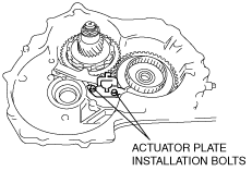
39. Remove the actuator plate.
d6e517za5015
|
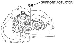
40. Remove the support actuator.
d6e517za5016
|
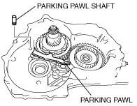
41. Pull out the parking pawl shaft.
d6e517za5017
|
42. Remove the parking pawl.
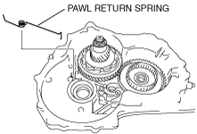
43. Remove the pawl return spring.
d6e517za5018
|
44. Remove the Output gear component.
d6j517za4039
|
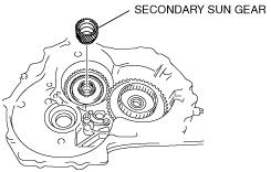
45. Remove the Secondary sun gear.
d6e517za5019
|
46. Remove the direct clutch component and one-way clutch No.2.
d6e517za5020
|
47. Remove the Needle bearing, seal rings and spacer.
d6e517za5021
|
48. Remove the reduction brake.(See REDUCTION BRAKE DISASSEMBLY/ASSEMBLY.)
49. Remove the end cover.
d6e517za5022
|
50. Remove the O-rings from the transaxle case.
51. Remove the band strut.
d6e517za5023
|
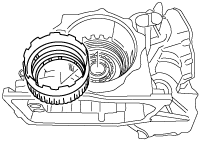
52. Remove the 2–4 brake band, and hold it together using a piece of wire as shown in the figure.
b3e0517a223
|
53. Remove the clutch component.
d6j517za4023
|
54. Remove the snap ring.
d6j517za4024
|
55. Remove the rear planetary gear component.
d6j517za4025
|
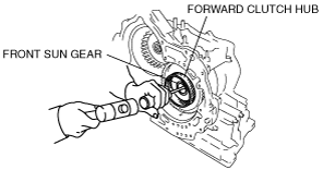
56. Remove the front sun gear by tapping its end with a flathead screwdriver or similar tool. as shown in the figure.
d6e517za5024
|
57. Remove the forward clutch hub.
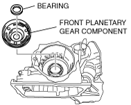
58. Remove the front planetary gear component.
d6e517za5025
|
59. Remove the front internal gear and one-way clutch component.
d6j517za4028
|
60. Remove the locknut.
b3e0517a230
|
d6e517za5026
|
d6e517za5027
|
d6j517za4030
|
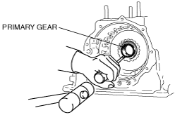
61. Remove the primary gear by tapping it with a flathead screwdriver, etc. as shown in the figure.
d6e517za5028
|
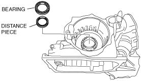
62. Remove the bearing and distance piece.
d6e517za5029
|
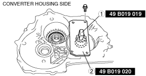
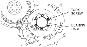
63. Remove torx screws from the converter housing side.
d6e517za5030
|
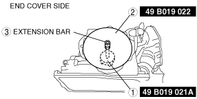
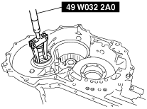
64. Remove the bearing race.
65. Remove the bearing race using the SST as shown in the figure.
d6j517za4032
|
66. Remove the bearing using the SST as shown in the figure.
d6j517za4175
|