 |
am6zzw00000933
ON-BOARD DIAGNOSTIC TEST [MZR 1.8, MZR 2.0, MZR 2.5]
id0102f4801000
DTC Reading Procedure
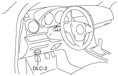
1. Connect the M-MDS (IDS) to the DLC-2.
am6zzw00000933
|
2. After the vehicle is identified, select the following items from the initialization screen of the IDS.
3. Then, select the “Retrieve CMDTCs” and perform procedures according to directions on the IDS screen.
4. Verify the DTC according to the directions on the IDS screen.
5. After completion of repairs, clear all DTCs stored in the PCM, while referring to “AFTER REPAIR PROCEDURE”.
Pending Trouble Code Access Procedure
1. Connect the M-MDS (IDS) to the DLC-2.
am6zzw00000933
|
2. After the vehicle is identified, select the following items from the initialization screen of the IDS.
3. Then, select the “Retrieve CMDTCs” and perform procedures according to directions on the IDS screen.
4. Retrieve the pending trouble codes according to the directions on the IDS screen.
Freeze Frame PID Data Access Procedure
1. Connect the M-MDS (IDS) to the DLC-2.
am6zzw00000933
|
2. After the vehicle is identified, select the following items from the initialization screen of the IDS.
3. Then, select the “Retrieve CMDTCs” and perform procedures according to directions on the IDS screen.
4. Retrieve the freeze frame PID data according to the directions on the IDS screen.
Freeze frame data table
|
Freeze frame data item |
Unit |
Description |
Corresponding PID data monitor item |
|---|---|---|---|
|
FUELSYS1
|
Open Loop/Closed Loop/OL-Drive/OL-Fault/CL-Fault
|
Fuel system status
|
FUELSYS
|
|
LOAD
|
%
|
Calculated engine load
|
—
|
|
ECT
|
°C, °F
|
Engine coolant temperature
|
ECT
|
|
SFT1
|
%
|
Short term fuel trim
|
SHRTFT1
|
|
LFT1
|
%
|
Long term fuel trim
|
LONGFT1
|
|
MAP
|
KPa, Bar, in Hg
|
Manifold absolute pressure
|
MAP
|
|
RPM
|
RPM
|
Engine speed
|
RPM
|
|
VS
|
KPH, MPH
|
Vehicle speed
|
VSS
|
|
SPARKADV
|
°
|
Ignition timing
|
SPARKADV
|
|
IAT
|
°C, °F
|
Intake air temperature
|
IAT
|
|
MAF
|
g/sec
|
Mass airflow
|
MAF
|
|
TP
|
%
|
Throttle valve position No.1
|
TP1
|
|
RUNTM
|
hh:mm:ss
|
Time from engine start
|
—
|
|
EGRPCT
|
%
|
Target EGR valve position
|
SEGRP_DSD
|
|
EVAPPCT
|
%
|
Purge solenoid valve controlled value
|
EVAPCP
|
|
WARMUPS
|
—
|
Number of warm-up cycle after DTC cleared
|
—
|
|
CLRDIST
|
Km, mi
|
Mileage after DTC cleared
|
—
|
|
CATTEMP11
|
°C, °F
|
Estimated catalytic converter temperature
|
CATT11_DSD
|
|
VPWR
|
V
|
Module supply voltage
|
VPWR
|
|
ALV
|
%
|
Engine load
|
LOAD
|
|
TP_REL
|
%
|
Relative throttle position
|
TP REL
|
|
TP_B
|
%
|
Throttle valve position No.2
|
TP2
|
|
APP_D
|
%
|
Accelerator pedal position No.1
|
APP1
|
|
APP_E
|
%
|
Accelerator pedal position No.2
|
APP2
|
|
TAC_PCT
|
%
|
Target throttle valve position
|
ETC_DSD
|
Snapshot data table
|
Snapshot data item |
Unit |
Definition |
Corresponding PID data monitor item |
|---|---|---|---|
|
FUELSYS
|
OL/CL/OL-Drive/OL-Fault/CL-Fault
|
Fuel system status
|
FUELSYS
|
|
LOAD_C
|
%
|
Calculated engine load
|
—
|
|
ECT
|
°C, °F
|
Engine coolant temperature
|
ECT
|
|
SHRTFT1
|
%
|
Short term fuel trim
|
SHRTFT1
|
|
LONGFT1
|
%
|
Long term fuel trim
|
LONGFT1
|
|
MAP
|
KPa, Bar, in Hg
|
Manifold absolute pressure
|
MAP
|
|
RPM
|
RPM
|
Engine speed
|
RPM
|
|
VSS
|
KPH, MPH
|
Vehicle speed
|
VSS
|
|
SPARKADV
|
°
|
Ignition timing
|
SPARKADV
|
|
IAT
|
°C, °F
|
Intake air temperature
|
IAT
|
|
MAF
|
g/sec
|
Mass airflow
|
MAF
|
|
TP1
|
%
|
Throttle valve position No.1
|
TP1
|
|
EG_RUN_TIME
|
—
|
Time from engine start
|
—
|
|
SEGRP_DSD
|
%
|
Target EGR valve position
|
SEGRP DSD
|
|
EVAPCP
|
%
|
Purge solenoid valve controlled value
|
EVAPCP
|
|
FLI
|
%
|
Fuel level in fuel tank
|
—
|
|
CLR_CNT
|
—
|
Number of warm-up cycle after DTC cleared
|
—
|
|
CLR_DIST
|
Km, mi
|
Mileage after DTC cleared
|
—
|
|
FTP
|
KPa, Bar, psi
|
Fuel tank pressure
|
—
|
|
BARO
|
KPa, Bar, psi
|
Barometric pressure
|
—
|
|
CATT11_DSD
|
°C, °F
|
Estimated catalytic converter temperature
|
CATT11_DSD
|
|
VPWR
|
V
|
Module supply voltage
|
VPWR
|
|
LOAD
|
%
|
Engine load
|
LOAD
|
|
EQ_RAT11_DSD
|
—
|
Target equivalence ratio (lambda)
|
EQ_RAT11_DSD
|
|
TP REL
|
%
|
Relative throttle position
|
TP REL
|
|
AAT
|
°C, °F
|
Ambient air temperature
|
—
|
|
TP2
|
%
|
Throttle valve position No.2
|
TP2
|
|
APP1
|
%
|
Accelerator pedal position No.1
|
APP1
|
|
APP2
|
%
|
Accelerator pedal position No.2
|
APP2
|
|
ETC_DSD
|
%
|
Target throttle valve position
|
ETC_DSD
|
On-Board System Readiness Tests Access Procedure
1. Connect the M-MDS (IDS) to the DLC-2.
am6zzw00000933
|
2. After the vehicle is identified, select the following items from the initialization screen of the IDS.
3. Then, select the “***SUP” and “**EVAL” PIDs in the PID selection screen.
4. Monitor those PIDs and check it system monitor is completed.
PID/DATA Monitor and Record Procedure
1. Connect the M-MDS (IDS) to the DLC-2.
am6zzw00000933
|
2. After the vehicle is identified, select the following items from the initialization screen of the IDS.
3. Select the applicable PID from the PID table.
4. Verify the PID data according to the detections on the screen.
Diagnostic Monitoring Test Results Access Procedure
1. Connect the M-MDS (IDS) to the DLC-2.
am6zzw00000933
|
2. After the vehicle is identified, select the following items from the initialization screen of the IDS.
3. Verify the diagnostic monitoring test result according to the directions on the IDS screen.
Active Command Modes Procedure
1. Connect the M-MDS (IDS) to the DLC-2.
am6zzw00000933
|
2. After the vehicle is identified, select the following items from the initialization screen of the IDS.
3. Select the simulation items from the PID table.
4. Perform the active command modes function, inspect the operations for each parts.