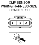
CAMSHAFT POSITION (CMP) SENSOR INSPECTION [MZR-CD 2.2]


id0140f2801400

Note
•  Perform the following test only when directed.
Caution
•  When foreign material, such as iron chips, gets on the CMP sensor, it can cause abnormal output from the sensor because of flux turbulence and adversely affect engine control. Be sure there is no foreign material on the CMP sensor when replacing.
•  Do not forcefully pull the wiring harness of the CMP sensor. Doing so will break the harness.

Visual Inspection

1.  Verify that the CMP sensor and the pulsar are free of any metallic shavings or particles.

•  If any are found on the CMP sensor and the pulsar, clean them off.


Air Gap Inspection

1.  Verify that the CMP sensor is securely installed.

2.  Using a thickness gauge, measure the air gap between the plate projections at the back of crankshaft pulley and the CMP sensor.

•  If not within the specification, inspect the plate projections for cracks or bending.
―   If there is any malfunction, replace the camshaft.

Air gap
0.5—1.5 mm {0.02—0.05 in}

Voltage inspection

1.  Idle the engine.

Caution
•  Water penetrating the connector will cause sensor malfunction. To prevent this, be careful not to damage the wiring harnesses or the waterproof connector so as to cause water penetration.

2.  Measure the output voltage using a oscilloscope.

am6zzw00004020

•  If not within the specification, replace the CMP sensor. (See CAMSHAFT POSITION (CMP) SENSOR REMOVAL/INSTALLATION [MZR-CD 2.2].)

CMP sensor voltage

Terminal

Voltage (V)

Condition

A
4.0 or more
High output
1.0 or less
Low output
B
0
Under any condition
C
5
Under any condition