acxuun00000052
|
FUEL INJECTION CONTROL OPERATION [MZR 2.0 DISI]
id0140j3101900
Operation
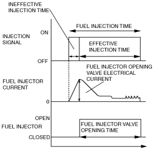
Injection timing
Injection Time
acxuun00000052
|
Determination of effective Injection Time
am3zzn00002816
|
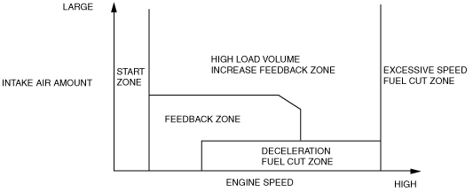
Start zone
Feedback zone
High load volume increase feedback zone
Excessive speed fuel cut zone
Deceleration fuel cut zone
Fuel injection time calculation method table
|
Contents
(Fuel injection time, calculation method, or determination method)
|
Control zone
|
||||||
 |
 |
 |
 |
 |
|||
|
Injection time at start
|
Set value according to engine coolant temperature (low engine coolant temperature→long injection time)
|
A
|
|
|
|
|
|
|
Basic injection time
|
Basic injection time = charging efficiency x fuel flow coefficient
|
|
A
|
A
|
|
|
|
|
Fuel cut
|
Fuel injection time = 0
|
|
|
|
A
|
A
|
|
|
Ineffective injection time
|
Set time according to injector performance
|
A
|
A
|
A
|
|
|
|
|
Volume increase correction at engine start
|
Purpose: Ensures engine speed stability just after engine start
Correction condition
• Specified time according to the engine coolant temperature directly after engine start
Correction amount
• Low engine coolant temperature→large correction
• High intake air temperature→large correction
|
B
|
B
|
|
|
|
|
|
A/F sensor feedback correction
|
Purpose: Controls air/fuel ratio to target air/fuel ratio
Correction condition
• When the engine coolant temperature is at the set value or more
Correction amount
• A/F sensor current value 0 mA or less→volume decrease correction
• A/F sensor current value 0 mA or more→volume increase correction
|
|
B
|
|
|
|
|
|
HO2S feedback correction
|
Purpose: Controls air/fuel ratio to theoretical air/fuel ratio correction condition
Correction condition
• When the engine coolant temperature is at the set value or more
Correction amount
• HO2S voltage value 0.45 V or less→volume increase correction
• HO2S voltage value 0.45 V or more→volume decrease correction
|
|
B
|
|
|
|
|
|
High load value increase feedback correction
|
Purpose: Improved engine output, decrease of exhaust gas temperature
Correction condition
• Based on the engine speed when the accelerator opening angle is the fixed value or more, otherwise, based on the engine speed and charging efficiency.
Correction amount
• High engine speed, high charging efficiency→large correction
|
|
|
B
|
|
|
|
|
Warm-up volume increase correction
|
Purpose: Ensures combustion stability when the engine coolant temperature is low
Correction condition
• While at the set engine coolant temperature
Correction amount
• High charging efficiency, low engine coolant temperature→large correction
|
|
B
|
B
|
|
|
|
|
A/C load increase correction
|
Purpose: Maintains engine speed stability during A/C operation
Correction condition
• A/C is operating
Correction amount
• Low engine coolant temperature→large correction
|
|
B
|
B
|
|
|
|
|
Volume increase correction during acceleration
|
Purpose: Corrects fuel injection delay during acceleration, to ensure drive stability
Correction condition
• When the acceleration amount (change in the amount of charging efficiency) is at the set value or more.
Correction amount
• Low engine coolant temperature→large correction
• Large acceleration amount→large correction
|
|
B
|
B
|
|
|
|
|
Learning correction
|
Purpose: Corrects deviation in air/fuel ratio from deterioration over time of mechanical devices
Correction condition
• Under any condition except purge control
Correction amount
• Learning value based on average of feedback correction value
|
|
B
|
B
|
|
|
|
|
Deceleration volume increase correction
|
Purpose: Ensures stability of engine speed during recovery from fuel cut
Correction condition
• Recovery from deceleration fuel cut
Correction amount
• High engine speed→small correction
|
|
B
|
|
|
|
|
Fuel Cut
Sensor damage fuel cut
Dechoke Control
Boost Circuit
Output Circuit
|
Fuel injector status |
Injector driver module operation |
|---|---|
|
Opening starts
|
1. Provides 65 V, boosted by the boost circuit, to the opening transistor (65 V output).
2. When the voltage is provided to the fuel injector and turns on the GND transistor, the fuel injector opens.
3. After the fuel injector is opened, the opening transistor is turned off.
|
|
Opening held
|
• Controls the on/off of the holding transistor (12 V output) so that the hold current of the fuel injector is constant.
|
|
Closing
|
• Turns off the holding and GND transistors at the same time the fuel injection signal from the PCM is stopped, and cuts the current.
|