 |
am6zzw00003659
FRONT WHEEL ALIGNMENT [Australian Specs. and General (L.H.D., R.H.D.) Specs.]
id021100800205
Specification (Unloaded)*1
Front wheel alignment [4SD and 5HB]
|
Item |
Specification |
|||||||
|---|---|---|---|---|---|---|---|---|
|
Fuel gauge indication |
Empty |
1/4 |
1/2 |
3/4 |
Full |
|||
|
Maximum steering angle
[Tolerance ±3°]
|
Inner
|
Equipped with 16-inch or 17-inch tire: 39°30′
Equipped with 18-inch tire: 37°24′
|
||||||
|
Outer
|
Equipped with 16-inch or 17-inch tire: 32°24′
Equipped with 18-inch tire: 31°12′
|
|||||||
|
Total toe-in
|
(mm {in})
|
Tire: 2±4 {0.08±0.16}, Rim inner: 1±3 {0.04±0.12}
|
||||||
|
(degree)
|
0°09′±18′
|
|||||||
|
Caster angle*2 (Reference value)
[Tolerance ±1°]
|
MZR 2.0 DISI (MTX)
|
4SD
|
3°30′
|
3°33′
|
3°35′
|
3°37′
|
||
|
5HB
|
3°33′
|
3°35′
|
3°38′
|
3°40′
|
||||
|
MZR 2.0 DISI (ATX) and MZR 2.5
|
4SD
|
3°29′
|
3°30′
|
3°32′
|
3°35′
|
3°37′
|
||
|
5HB
|
3°32′
|
3°33′
|
3°35′
|
3°37′
|
3°39′
|
|||
|
MZR-CD 2.2
|
4SD
|
3°28′
|
3°29′
|
3°31′
|
3°34′
|
3°36′
|
||
|
5HB
|
3°32′
|
3°34′
|
3°36′
|
3°38′
|
||||
|
Camber angle*2
(Reference value) [Tolerance ±1°]
|
MZR 2.0 DISI (MTX)
|
-0°15′
|
-0°16′
|
|||||
|
MZR 2.0 DISI (ATX) and MZR 2.5
|
-0°16′
|
-0°17′
|
||||||
|
MZR-CD 2.2
|
-0°18′
|
-0°19′
|
||||||
|
Steering axis inclination (Reference value) [Tolerance ±1°]
|
MZR DISI and MZR 2.5
|
6°36′
|
6°37′
|
|||||
|
MZR-CD 2.2
|
6°38′
|
6°39′
|
||||||
Front wheel alignment [WGN]
|
Item |
Specification |
|||||||
|---|---|---|---|---|---|---|---|---|
|
Fuel gauge indication |
Empty |
1/4 |
1/2 |
3/4 |
Full |
|||
|
Maximum steering angle
[Tolerance ±3°]
|
Inner
|
Equipped with 16-inch or 17-inch tire: 39°30′
Equipped with 18-inch tire: 37°24′
|
||||||
|
Outer
|
Equipped with 16-inch or 17-inch tire: 32°24′
Equipped with 18-inch tire: 31°12′
|
|||||||
|
Total toe-in
|
(mm {in})
|
Tire: 2±4 {0.08±0.16}, Rim inner: 1±3 {0.04±0.12}
|
||||||
|
(degree)
|
0°09′±18′
|
|||||||
|
Caster angle*2 (Reference value)
[Tolerance ±1°]
|
MZR 2.0 DISI (ATX) and MZR 2.5
|
3°21′
|
3°23′
|
3°25′
|
3°27′
|
|||
|
MZR-CD 2.2
|
3°19′
|
3°21′
|
3°23′
|
3°25′
|
||||
|
Camber angle*2 (Reference value)
[Tolerance ±1°]
|
MZR 2.0 DISI (ATX) and MZR 2.5
|
-0°13′
|
-0°14′
|
|||||
|
MZR-CD 2.2
|
-0°15′
|
-0°16′
|
||||||
|
Steering axis inclination (Reference value)
[Tolerance ±1°]
|
MZR DISI and MZR 2.5
|
6°33′
|
6°34′
|
|||||
|
MZR-CD 2.2
|
6°36′
|
6°37′
|
||||||
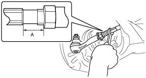
Maximum Steering Angle Adjustment
1. Loosen the tie-rod end locknuts.
2. Remove the steering gear boot clamp.
3. Turn the tie rods.
am6zzw00003659
|
4. Turn the tie rods equally to provide the correct maximum steering angle.
5. Tighten the tie-rod end locknuts.
6. Verify that the boot is not twisted, and install the boot clamp.
7. Adjust the toe-in after adjusting the steering angle.
Total Toe-in Adjustment
1. Center the steering wheel and confirm that the vehicle wheels/tires are pointing straight.
2. Loosen the left and right tie-rod end locknuts and turn the tie-rods equally. Both tie rods are right threaded, so turning the right tie-rod toward the front of the vehicle and the left toward the rear increases toe-in.
3. Tighten the tie-rod end locknuts to the specified torque.
4. Verify that the boot is not twisted, and install the boot clamp.