VEHICLE SPEED SENSOR (VSS) INSPECTION [FS5A-EL]
id051721801400
-
Caution
-
• Water or foreign objects entering the connector can cause a poor connection or corrosion. Be sure not to drop water or foreign objects on the connector when disconnecting it.
On-Vehicle Inspection
1. Inspect the power supply circuit for the VSS.
- (1) Remove the aerodynamic under cover NO.2. (See AERODYNAMIC UNDER COVER NO.2 REMOVAL/INSTALLATION.)
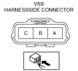
- (2) Disconnect the VSS connector.
-
- (3) Switch the ignition to ON. (engine off)
- (4) Measure the voltage at VSS connector terminal A (harness side).
-
-
• If there is any malfunction, repair wiring harness between VSS and TCM.
- (5) Switch the ignition to off.
- (6) Connect the VSS connector.
2. Inspect the GND circuit for the VSS.
- (1) Switch the ignition to off.
- (2) Measure the voltage at VSS connector terminal C (harness side).
-
-
• If there is any malfunction, repair wiring harness between VSS and TCM.
-
VSS specification
Below 1.0 V
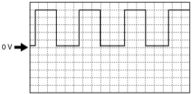
3. Inspect the signal circuit for the VSS.
- (1) Connect the oscilloscope to the following TCM connector terminals and set it as below.
-
-
• (+) lead: TCM terminal 2P
• (–) lead: body GND
• Oscilloscope setting: 1 V/DIV (Y), 2 ms/DIV (X), DC range
- (2) Start the engine.
- (3) Measure the wave form when the following conditions are met.
-
-
― Vehicle speed: 30 km/h {19 mph}
― 3 GR
-