 |
am6zzw00007936
STEERING GEAR AND LINKAGE ADJUSTMENT
id061300290000
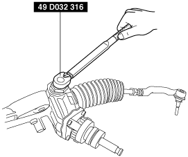
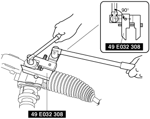
1. Remove the locknut using the SST.
am6zzw00007936
|
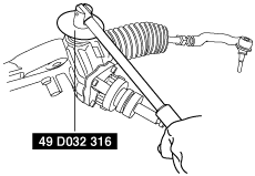
2. Apply sealant to the threads of the adjustment cover.
3. Tighten the adjustment cover to 20—29 N·m {2.1—2.9 kgf·m, 15—21 ft·lbf}.
am6zzw00003700
|
4. After swinging the steering rack left and right 10 times, tighten the adjustment cover again to 5.8 N·m {59 kgf·cm, 51 in·lbf}.
5. Loosen the adjustment cover 10—20°.
am6zzw00001707
|
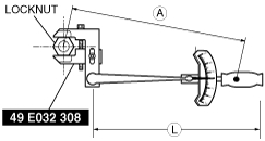
6. Combine the the SST with the torque wrench, then measure A and L as shown in the figure.
am6zzw00007935
|
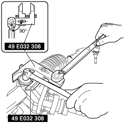
7. Recalculate the torque by using torque formulas, then lock the adjustment cover against rotation and tighten the locknut using the SST.
am6zzw00007937
|
Torque formula
|
Torque unit |
Formula |
|---|---|
|
N·m
|
N·m×[L/A]
|
|
kgf·m
|
kgf·m×[L/A]
|
|
ft·lbf
|
ft·lbf×[L/A]
|
8. Measure the pinion shaft rotational torque using the SST and a pull scale.
am6zzw00003698
|