 |
am6zzw00007419
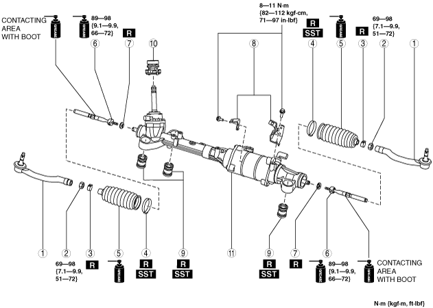
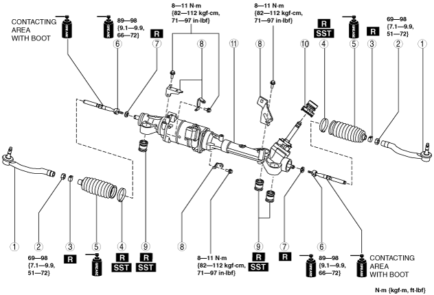
STEERING GEAR AND LINKAGE DISASSEMBLY/ASSEMBLY
id061300801900
1. Disassemble in the order indicated in the table.
2. Assemble in the reverse order of disassembly.
L.H.D.
am6zzw00007419
|
R.H.D.
am6zzw00007420
|
|
1
|
Tie-rod end
(See Tie-rod End Disassembly Note.)
(See Tie-rod End Assembly Note.)
|
|
2
|
Locknut
|
|
3
|
Boot clamp
|
|
4
|
Boot band
(See Boot Band Assembly Note.)
|
|
5
|
Boot
|
|
6
|
Tie rod
|
|
7
|
Lock washer
|
|
8
|
Bracket
|
|
9
|
Mounting rubber
|
|
10
|
Dust cover
(See Dust Cover Assembly Note.)
|
|
11
|
Steering gear
|
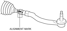
Tie-rod End Disassembly Note
1. Place alignment marks as shown in the figure for proper installation.
am6zzw00002137
|
2. Remove the tie-rod end.
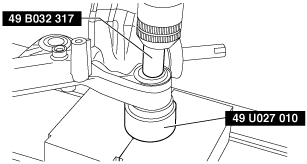
Mounting Rubber Disassembly Note
1. Press the mounting rubber out from the gear housing using the SSTs and a press.
am6zzw00001700
|
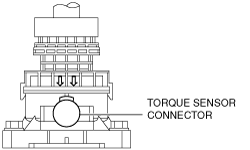
Dust Cover Assembly Note
1. Assemble with the arrow on the dust cover aligned to the torque sensor connector.
am6zzw00006305
|
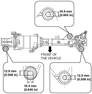
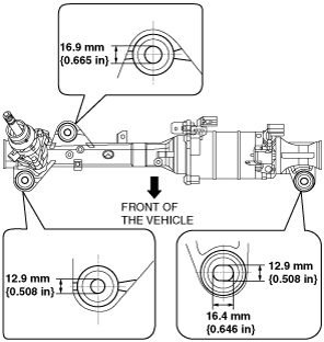
Mounting Rubber Assembly Note
1. Apply soapy water to the rubber part of the mounting rubber.
2. Temporarily install the steering gear so that the mounting rubber are in the positions shown in the figure.
L.H.D.
am6zzw00007282
|
R.H.D.
am6zzw00007283
|
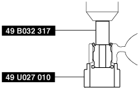
3. Press the mounting rubber until the mounting rubber end comes out completely from the gear housing using the SSTs and a press.
am6zzw00001701
|
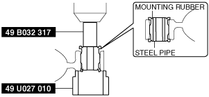
4. Reverse the gear housing, then press the mounting rubber until the mounting rubber end comes out completely from the other side. At this time, make sure that the mounting rubber and steel pipe are aligned.
am6zzw00001702
|
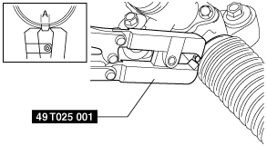
Boot Band Assembly Note
1. Crimp the boot band using the SST.
am6zzw00001703
|
2. Verify that the crimping clearance A is within the specification.
3. Rotate the boot by hand and verify that it is securely installed to the boot band.
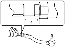
Tie-rod End Assembly Note
1. Align the alignment marks made before removal and assemble the tie-rod end to the tie rod.
am6zzw00002137
|
2. Adjust dimension A shown in the figure to the standard, then assemble the tie-rod end.
am6zzw00002138
|