 |
am6zzw00002915
MAGNETIC CLUTCH DISASSEMBLY/ASSEMBLY [FULL-AUTO AIR CONDITIONER]
id0740a1800400
MZR 1.8, MZR 2.0, MZR 2.0 DISI, MZR 2.5
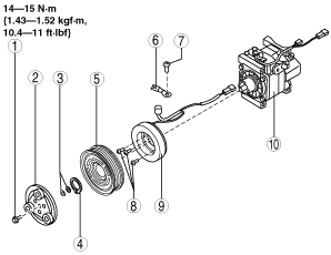
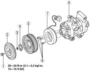
1. Disassemble in the order indicated in the table.
am6zzw00002915
|
|
1
|
Bolt
|
|
2
|
Pressure plate
|
|
3
|
Shim
(See Shim installation note.)
|
|
4
|
Snap ring
|
|
5
|
A/C compressor pulley
|
|
6
|
Screw
|
|
7
|
Stator
|
|
8
|
A/C compressor body
|
2. Assemble in the reverse order of disassembly.
3. Adjust the magnetic clutch clearance. (See MAGNETIC CLUTCH ADJUSTMENT [FULL-AUTO AIR CONDITIONER].)
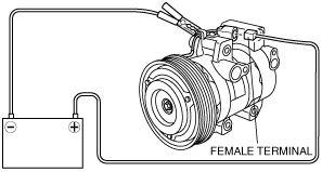
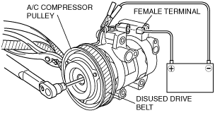
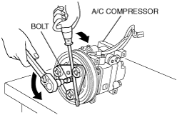
Bolt removal/installation note
1. When removing or installing the bolt, lock the A/C compressor pulley against rotation using the following procedure.
am6zzw00001938
|
am6zzw00001939
|
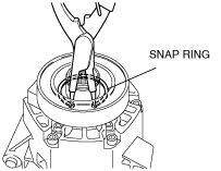
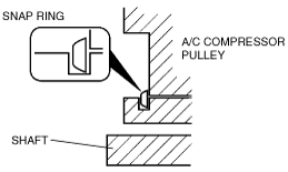
Snap ring removal/installation note
1. Remove/installation the snap ring using a snap ring pliers.
am6zzw00001060
|
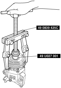
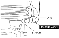
A/C compressor pulley removal note
1. Remove the A/C compressor pulley using the SSTs (49 0839 425C, 49 U027 001).
am6zzw00001061
|
am6zzw00001940
|
A/C compressor pulley installation note
1. Install the inner wheel of the pulley using a press and SST (49 B034 212) to the compressor.
am6zzw00003850
|
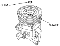
Shim installation note
1. First, insert the 1mm (0.039 in) thick shim into the shaft.
am6zzw00006679
|
MZR-CD 2.2
1. Disassemble in the order indicated in the table.
am6zzw00006680
|
|
1
|
Bolt
|
|
2
|
Pressure plate
|
|
3
|
Shim
|
|
4
|
Snap ring
(See Snap ring installation note.)
|
|
5
|
A/C compressor pulley
|
|
6
|
Clamp
(See Clamp installation note.)
|
|
7
|
Screw
(See Screw installation note.)
|
|
8
|
Screw
|
|
9
|
Stator and thermal protector
|
|
10
|
A/C compressor body
|
2. Assemble in the reverse order of disassembly.
3. Adjust the magnetic clutch clearance. (See MAGNETIC CLUTCH ADJUSTMENT [FULL-AUTO AIR CONDITIONER].)
Bolt removal/installation note
1. When removing or installing the bolt, hold the pressure plate in place as shown in the figure.
am6zzw00006681
|
2. When installing a new A/C compressor body, replace the recommended bolt.
Thermal protector removal note
1. After removing the stator and thermal protector, completely remove the silicone adhering to the A/C compressor side.
Thermal protector installation note
1. Apply approx. 1g {0.04 oz} of silicone (Shin-Etsu Silicone KE-347W or similar) to the contact surface of the thermal protector, then thoroughly install it onto the A/C compressor, leaving no gaps.
am6zzw00006682
|
Screw installation note
1. When installing a new thermal protector, replace the screw.
Clamp installation note
1. When installing a new thermal protector, replace the clamp.
Snap ring installation note
1. When installing a new pressure plate, A/C compressor pulley, stator, or A/C compressor body, replace the snap ring.
am5ezw00001253
|