 |
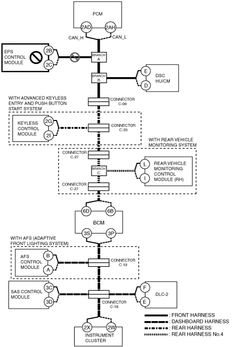
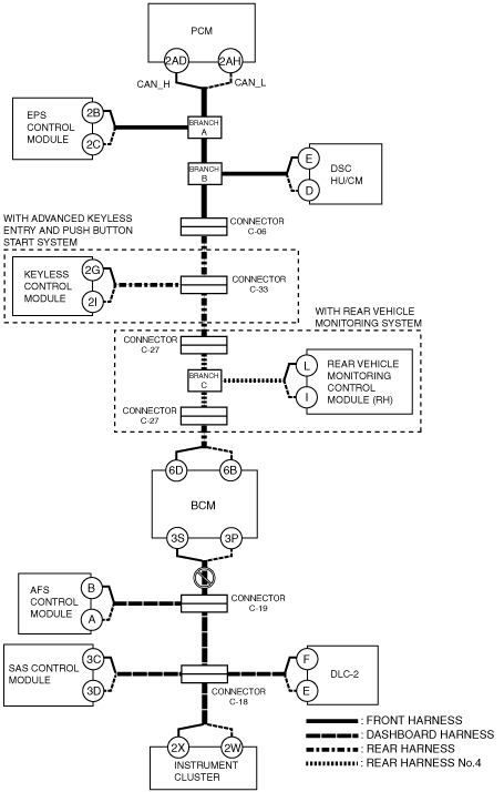
am6zzw00006560
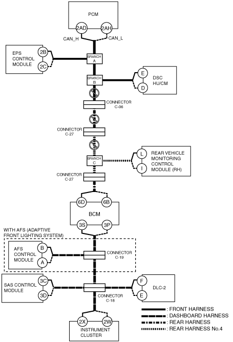
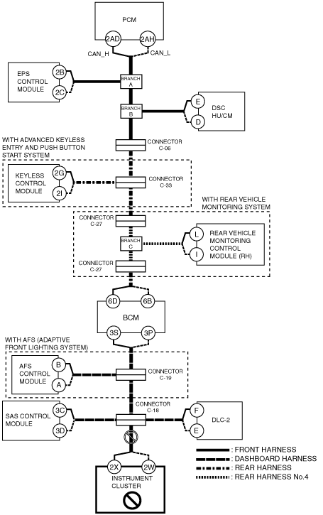
DETERMINING MALFUNCTIONING PART (HS-CAN) [MULTIPLEX COMMUNICATION SYSTEM (R.H.D. (MZR-CD 2.2))]
id0902k5846700
1. Verify the CAN system-related module DTCs and the failed module using the (M-MDS).
2. Look for a DTC display pattern and failed module display pattern in tandem which match.
3. Refer to the matching tandem diagnostic results (A to O) and inspect the possible cause and inspection item.
4. Perform the DTC inspection after the repair procedure.
DTC Output Pattern and Malfunctioning Part
|
M-MDS display |
DTC display pattern |
|||||||||||||||
|---|---|---|---|---|---|---|---|---|---|---|---|---|---|---|---|---|
|
DTC output module |
DTC |
|||||||||||||||
|
PCM
(PCM)
|
U0121:00
|
|
|
|
×
|
|
|
|
|
|
|
|
|
|
|
|
|
U0155:00
|
|
|
|
|
|
|
|
|
|
|
|
|
|
|
×
|
|
|
EPS
(EPS control module)
|
U0100:00
|
×
|
|
|
|
|
|
|
|
|
|
|
|
|
|
|
|
U0300:00
|
-
|
|
|
|
|
|
|
|
|
|
|
|
|
|
|
|
|
U0401:00
|
-
|
|
|
|
|
|
|
|
|
|
|
|
|
|
|
|
|
U2100:00
|
-
|
|
|
|
|
|
|
|
|
|
|
|
|
|
|
|
|
U3000:85
|
-
|
|
|
|
|
|
|
|
|
|
|
|
|
|
|
|
|
ABS
(DSC HU/CM)
|
U0100:00
|
×
|
|
×
|
|
|
|
|
|
|
|
|
|
|
|
|
|
U0140:00
|
|
|
|
|
|
|
|
|
|
×
|
|
|
|
|
|
|
|
U0155:00
|
|
|
|
|
|
|
|
|
|
|
|
|
|
|
×
|
|
|
U0214:00
|
|
|
|
|
|
×
|
|
|
|
|
|
|
|
|
|
|
|
U0401:00
|
-
|
|
-
|
|
|
|
|
|
|
|
|
|
|
|
|
|
|
U0401:68
|
-
|
|
-
|
|
|
|
|
|
|
|
|
|
|
|
|
|
|
U0402:00
|
-
|
|
-
|
|
|
|
|
|
|
|
|
|
|
|
|
|
|
RKE*1
(Keyless control module)
|
U0100:00
|
×
|
|
×
|
|
×
|
|
|
|
|
|
|
|
|
|
|
|
U0121:00
|
|
|
|
×
|
×
|
|
|
|
|
|
|
|
|
|
|
|
|
RVM*2
(Rear vehicle monitoring control module (RH))
|
U0100:00
|
×
|
|
×
|
|
×
|
|
×
|
|
|
|
|
|
|
|
|
|
U0121:00
|
|
|
|
×
|
×
|
|
×
|
|
|
|
|
|
|
|
|
|
|
U0140:00
|
|
|
|
|
|
|
|
|
|
×
|
|
|
|
|
|
|
|
U0155:00
|
|
|
|
|
|
|
|
|
|
|
|
|
|
|
×
|
|
|
U0401:68
|
-
|
|
-
|
|
-
|
|
-
|
|
|
|
|
|
|
|
|
|
|
U0415:68
|
|
|
|
-
|
-
|
|
-
|
|
|
|
|
|
|
|
|
|
|
BCM/GEM
(BCM)
|
U0100:00
|
×
|
|
×
|
|
×
|
|
×
|
|
×
|
|
|
|
|
|
|
|
U0121:00
|
|
|
|
×
|
×
|
|
×
|
|
×
|
|
|
|
|
|
|
|
|
U0151:00
|
|
|
|
|
|
|
|
|
|
|
|
|
|
×
|
|
|
|
U0214:00
|
|
|
|
|
|
×
|
×
|
|
×
|
|
|
|
|
|
|
|
|
U0401:68
|
-
|
|
-
|
|
-
|
|
-
|
|
-
|
|
|
|
|
|
|
|
|
AFS*3
(AFS control module)
|
U0100:00
|
×
|
|
×
|
|
×
|
|
×
|
|
×
|
|
×
|
|
|
|
|
|
U0140:00
|
|
|
|
|
|
|
|
|
|
×
|
×
|
|
|
|
|
|
|
U0155:00
|
|
|
|
|
|
|
|
|
|
|
|
|
|
|
×
|
|
|
U0401:00
|
-
|
|
-
|
|
-
|
|
-
|
|
-
|
|
-
|
|
|
|
|
|
|
U0422:00
|
|
|
|
|
|
|
|
|
|
-
|
-
|
|
|
|
|
|
|
RCM
(SAS control module)
|
U0155:00
|
|
|
|
|
|
|
|
|
|
|
|
|
|
|
×
|
|
IC
(Instrument cluster)
|
U0100:00
|
×
|
|
×
|
|
×
|
|
×
|
|
×
|
|
×
|
|
×
|
|
|
|
U0100:87
|
-
|
|
-
|
|
-
|
|
-
|
|
-
|
|
-
|
|
-
|
|
|
|
|
U0121:00
|
|
|
|
×
|
×
|
|
×
|
|
×
|
|
×
|
|
×
|
|
|
|
|
U0140:00
|
|
|
|
|
|
|
|
|
|
×
|
×
|
|
×
|
|
|
|
|
U0151:00
|
|
|
|
|
|
|
|
|
|
|
|
|
|
×
|
|
|
|
U0182:00
|
|
|
|
|
|
|
|
|
|
|
|
×
|
×
|
|
|
|
|
U0214:00
|
|
|
|
|
|
×
|
×
|
|
×
|
|
×
|
|
×
|
|
|
|
|
U0232:00
|
|
|
|
|
|
|
|
×
|
×
|
|
×
|
|
×
|
|
|
|
|
U0401:68
|
-
|
|
-
|
|
-
|
|
-
|
|
-
|
|
-
|
|
-
|
|
|
|
|
U0401:92
|
-
|
|
-
|
|
-
|
|
-
|
|
-
|
|
-
|
|
-
|
|
|
|
|
U0415:68
|
|
|
|
-
|
-
|
|
-
|
|
-
|
|
-
|
|
-
|
|
|
|
|
U0415:92
|
|
|
|
-
|
-
|
|
-
|
|
-
|
|
-
|
|
-
|
|
|
|
|
U0452:92
|
|
|
|
|
|
|
|
|
|
|
|
|
|
-
|
|
|
|
U0483:68
|
|
|
|
|
|
|
|
|
|
|
|
-
|
-
|
|
|
|
|
U0483:92
|
|
|
|
|
|
|
|
|
|
|
|
-
|
-
|
|
|
|
|
U0515:68
|
|
|
|
|
|
-
|
-
|
|
-
|
|
-
|
|
-
|
|
|
|
|
U0515:92
|
|
|
|
|
|
-
|
-
|
|
-
|
|
-
|
|
-
|
|
|
|
|
U0533:68
|
|
|
|
|
|
|
|
-
|
-
|
|
-
|
|
-
|
|
|
|
|
U2005:86
|
-
|
|
-
|
|
-
|
|
-
|
|
-
|
|
-
|
|
-
|
|
|
|
|
M-MDS display module
|
“Fail” display pattern
|
|||||||||||||||
|
PCM
|
×
|
|
×
|
|
×
|
|
×
|
|
×
|
|
×
|
|
×
|
|
|
|
|
EPS
|
|
×
|
×
|
|
×
|
|
×
|
|
×
|
|
×
|
|
×
|
|
|
|
|
ABS
|
|
|
|
×
|
×
|
|
×
|
|
×
|
|
×
|
|
×
|
|
|
|
|
RKE*1
|
|
|
|
|
|
×
|
×
|
|
×
|
|
×
|
|
×
|
|
|
|
|
RVM*2
|
|
|
|
|
|
|
|
×
|
×
|
|
×
|
|
×
|
|
|
|
|
BCM/GEM
|
|
|
|
|
|
|
|
|
|
×
|
×
|
|
×
|
|
|
|
|
AFS*3
|
|
|
|
|
|
|
|
|
|
|
|
×
|
×
|
|
|
|
|
RCM
|
|
|
|
|
|
|
|
|
|
|
|
|
|
×
|
|
|
|
IC
|
|
|
|
|
|
|
|
|
|
|
|
|
|
|
×
|
|
|
Item
|
Diagnostic result
|
|||||||||||||||
|
Possible cause and inspection item
|
A
|
B
|
C
|
D
|
E
|
F
|
G
|
H
|
I
|
J
|
K
|
L
|
M
|
N
|
O
|
|
|
Reference page
|
||||||||||||||||
A
Possible cause
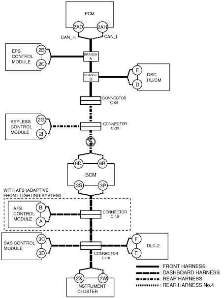
System wiring diagram
am6zzw00006560
|
Inspection item
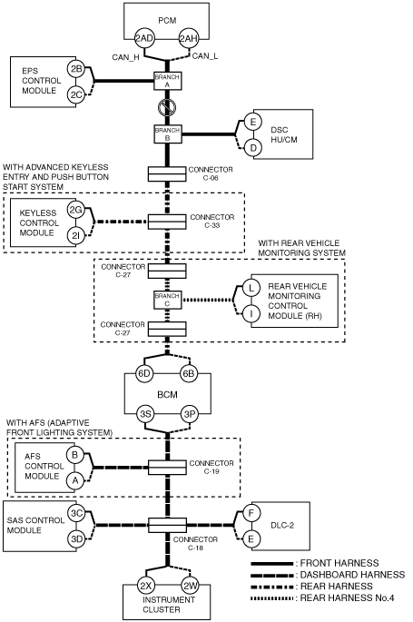
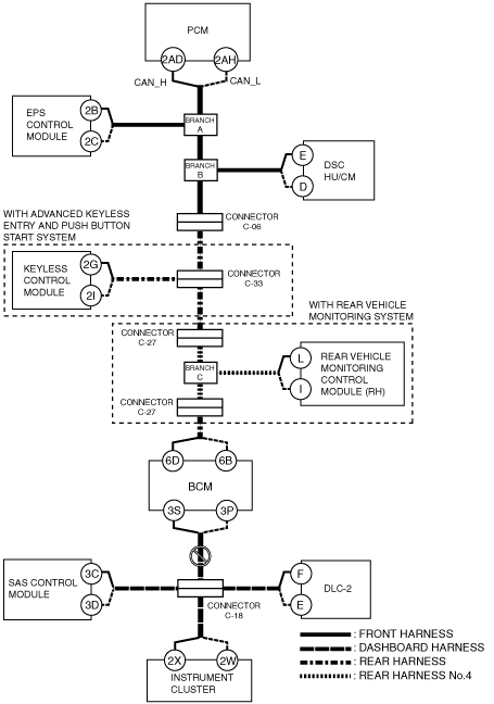
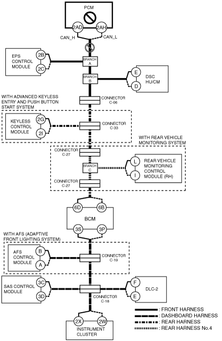
B
Possible cause
System wiring diagram
am6zzw00006561
|
Inspection item
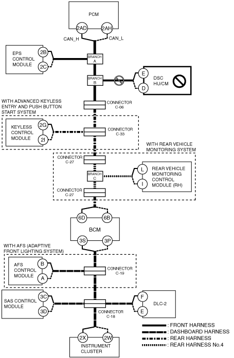
C
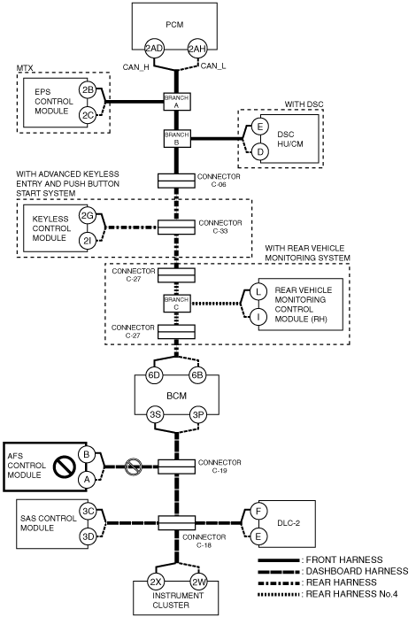
Possible cause
System wiring diagram
am6zzw00006562
|
Inspection item
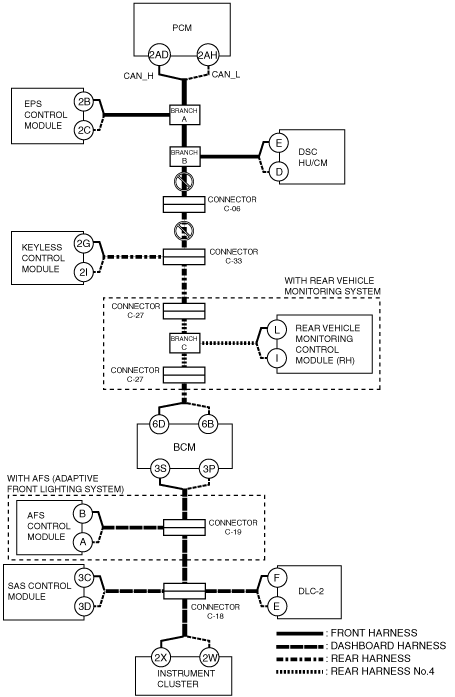
D
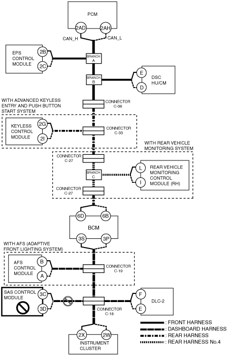
Possible cause
System wiring diagram
am6zzw00006563
|
Inspection item
E
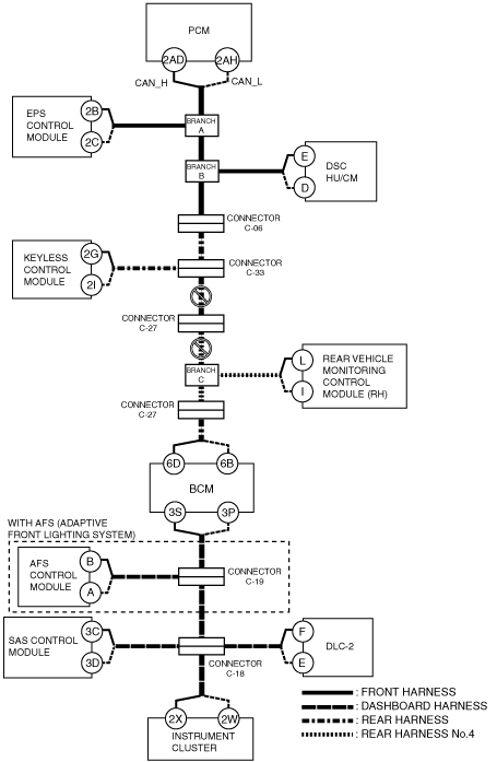
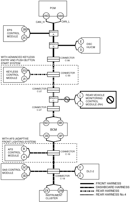
With advanced keyless entry and push button start system
System wiring diagram
am6zzw00006564
|
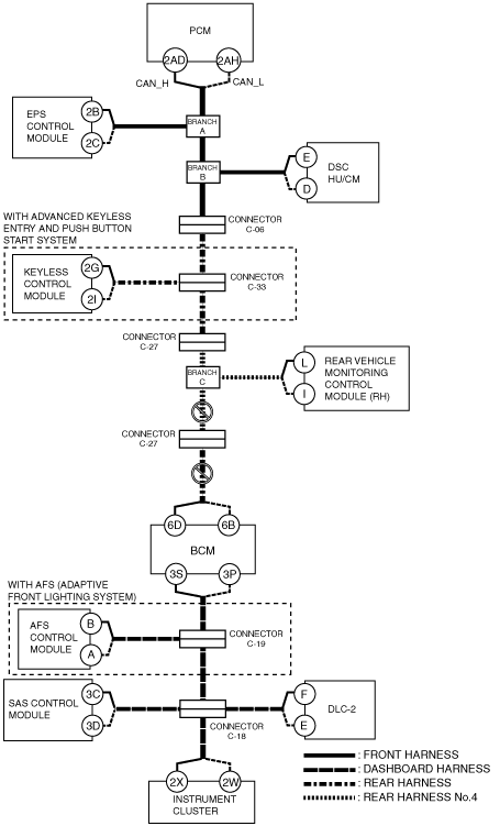
Without advanced keyless entry and push button start system
System wiring diagram
am6zzw00006565
|
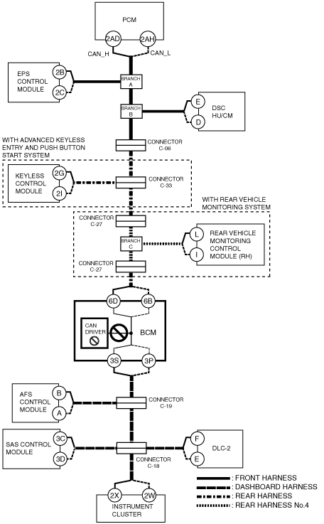
Without advanced keyless entry and push button start system and rear vehicle monitoring system
System wiring diagram
am6zzw00006566
|
F
Possible cause
System wiring diagram
am6zzw00006567
|
Inspection item
G
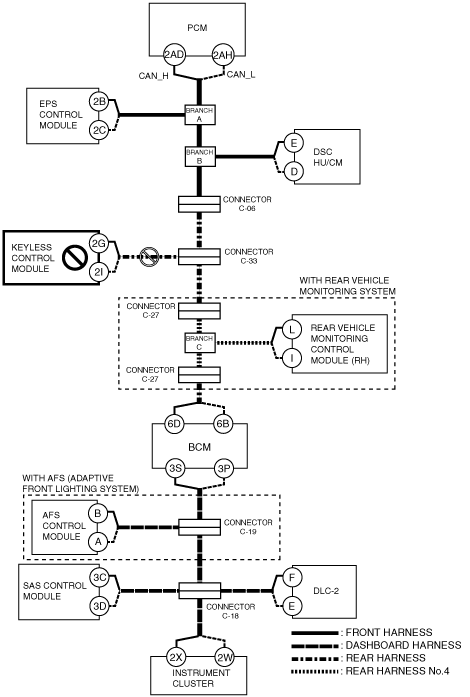
With rear vehicle monitoring system
System wiring diagram
am6zzw00006568
|
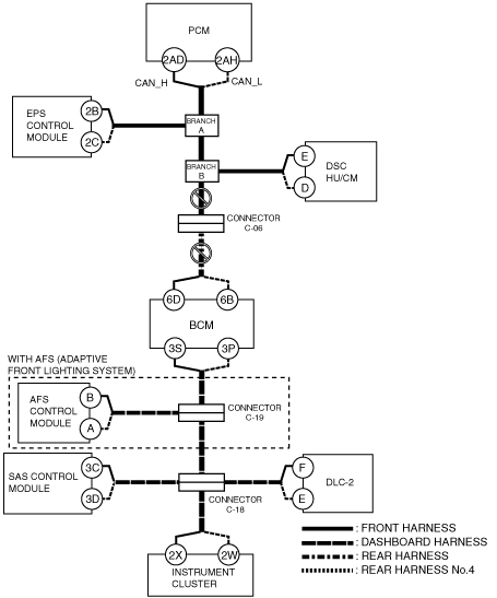
Without rear vehicle monitoring system
System wiring diagram
am6zzw00006569
|
H
Possible cause
System wiring diagram
am6zzw00006570
|
Inspection item
I
Possible cause
System wiring diagram
am6zzw00006571
|
Inspection item
J
Possible cause
System wiring diagram
am6zzw00006572
|
Inspection item
K
With AFS system
System wiring diagram
am6zzw00006573
|
Without AFS system
System wiring diagram
am6zzw00006574
|
L
Possible cause
System wiring diagram
am6zzw00006575
|
Inspection item
M
Possible cause
System wiring diagram
am6zzw00006576
|
Inspection item
N
Possible cause
System wiring diagram
am6zzw00006577
|
Inspection item
O
Possible cause
System wiring diagram
am6zzw00006578
|
Inspection item