 |
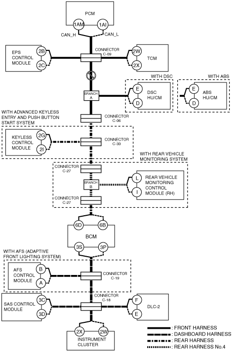
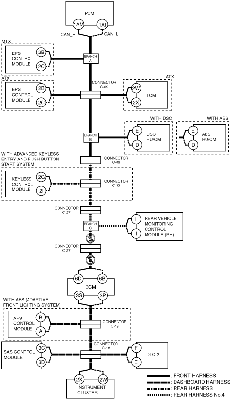
am6zzw00006608
DETERMINING MALFUNCTIONING PART (HS-CAN) [MULTIPLEX COMMUNICATION SYSTEM (R.H.D. (EXCEPT MZR-CD 2.2, MZR 2.0 DISI))]
id0902l8846700
1. Verify the CAN system-related module DTCs and the failed module using the (M-MDS).
2. Look for a DTC display pattern and failed module display pattern in tandem which match.
3. Refer to the matching tandem diagnostic results (A to Q) and inspect the possible cause and inspection item.
4. Perform the DTC inspection after the repair procedure.
DTC Output Pattern and Malfunctioning Part
|
M-MDS display |
DTC display pattern |
|||||||||||||||||
|---|---|---|---|---|---|---|---|---|---|---|---|---|---|---|---|---|---|---|
|
DTC output module |
DTC |
|||||||||||||||||
|
PCM
(PCM)
|
U0101:00
|
|
|
|
×
|
|
|
|
|
|
|
|
|
|
|
|
|
|
|
U0121:00
|
|
|
|
|
|
×
|
|
|
|
|
|
|
|
|
|
|
|
|
|
U0131:00
|
|
×
|
|
|
|
|
|
|
|
|
|
|
|
|
|
|
|
|
|
U0140:00
|
|
|
|
|
|
|
|
|
|
|
|
×
|
|
|
|
|
|
|
|
U0151:00
|
|
|
|
|
|
|
|
|
|
|
|
|
|
|
|
×
|
|
|
|
U0155:00
|
|
|
|
|
|
|
|
|
|
|
|
|
|
|
|
|
×
|
|
|
EPS
(EHPAS control module)
|
U0100:00
|
×
|
|
|
|
|
|
|
|
|
|
|
|
|
|
|
|
|
|
U0300:00
|
-
|
|
|
|
|
|
|
|
|
|
|
|
|
|
|
|
|
|
|
U0401:00
|
-
|
|
|
|
|
|
|
|
|
|
|
|
|
|
|
|
|
|
|
U2100:00
|
-
|
|
|
|
|
|
|
|
|
|
|
|
|
|
|
|
|
|
|
U3000:85
|
-
|
|
|
|
|
|
|
|
|
|
|
|
|
|
|
|
|
|
|
TCM*1
(TCM)
|
U0100:00
|
×
|
|
|
|
|
|
|
|
|
|
|
|
|
|
|
|
|
|
U0121:00
|
|
|
|
|
|
×
|
|
|
|
|
|
|
|
|
|
|
|
|
|
U0401:00
|
-
|
|
|
|
|
|
|
|
|
|
|
|
|
|
|
|
|
|
|
U0415:00
|
|
|
|
|
|
-
|
|
|
|
|
|
|
|
|
|
|
|
|
|
ABS*2
(DSC HU/CM)
|
U0100:00
|
×
|
|
×
|
|
×
|
|
|
|
|
|
|
|
|
|
|
|
|
|
U0101:00
|
|
|
|
×
|
×
|
|
|
|
|
|
|
|
|
|
|
|
|
|
|
U0140:00
|
|
|
|
|
|
|
|
|
|
|
|
×
|
|
|
|
|
|
|
|
U0155:00
|
|
|
|
|
|
|
|
|
|
|
|
|
|
|
|
|
×
|
|
|
U0214:00
|
|
|
|
|
|
|
|
×
|
|
|
|
|
|
|
|
|
|
|
|
U0401:00
|
-
|
|
-
|
|
-
|
|
|
|
|
|
|
|
|
|
|
|
|
|
|
U0401:68
|
-
|
|
-
|
|
-
|
|
|
|
|
|
|
|
|
|
|
|
|
|
|
U0402:00
|
-*7
|
|
-
|
-
|
-
|
|
|
|
|
|
|
|
|
|
|
|
|
|
|
ABS*3
(ABS HU/CM)
|
U0214:00
|
|
|
|
|
|
|
|
×
|
|
|
|
|
|
|
|
|
|
|
RKE*4
(Keyless control module)
|
U0100:00
|
×
|
|
×
|
|
×
|
|
×
|
|
|
|
|
|
|
|
|
|
|
|
U0101:00
|
|
|
|
×
|
×
|
|
×
|
|
|
|
|
|
|
|
|
|
|
|
|
U0121:00
|
|
|
|
|
|
×
|
×
|
|
|
|
|
|
|
|
|
|
|
|
|
RVM*5
(Rear vehicle monitoring control module (RH))
|
U0100:00
|
×
|
|
×
|
|
×
|
|
×
|
|
×
|
|
|
|
|
|
|
|
|
|
U0101:00
|
|
|
|
×
|
×
|
|
×
|
|
×
|
|
|
|
|
|
|
|
|
|
|
U0121:00
|
|
|
|
|
|
×
|
×
|
|
×
|
|
|
|
|
|
|
|
|
|
|
U0140:00
|
|
|
|
|
|
|
|
|
|
|
|
×
|
|
|
|
|
|
|
|
U0155:00
|
|
|
|
|
|
|
|
|
|
|
|
|
|
|
|
|
×
|
|
|
U0401:68
|
-
|
|
-
|
|
-
|
|
-
|
|
-
|
|
|
|
|
|
|
|
|
|
|
U0402:68
|
|
|
|
-
|
-
|
|
-
|
|
-
|
|
|
|
|
|
|
|
|
|
|
U0415:68
|
|
|
|
|
|
-
|
-
|
|
-
|
|
|
|
|
|
|
|
|
|
|
GEM
(BCM)
|
U0100:00
|
×
|
|
×
|
|
×
|
|
×
|
|
×
|
|
×
|
|
|
|
|
|
|
|
U0101:00
|
|
|
|
×
|
×
|
|
×
|
|
×
|
|
×
|
|
|
|
|
|
|
|
|
U0121:00
|
|
|
|
|
|
×
|
×
|
|
×
|
|
×
|
|
|
|
|
|
|
|
|
U0151:00
|
|
|
|
|
|
|
|
|
|
|
|
|
|
|
|
×
|
|
|
|
U0214:00
|
|
|
|
|
|
|
|
×
|
×
|
|
×
|
|
|
|
|
|
|
|
|
U0401:68
|
-
|
|
-
|
|
-
|
|
-
|
|
-
|
|
-
|
|
|
|
|
|
|
|
|
U0402:68
|
|
|
|
-
|
-
|
|
-
|
|
-
|
|
-
|
|
|
|
|
|
|
|
|
AFS*6
(AFS control module)
|
U0100:00
|
×
|
|
×
|
|
×
|
|
×
|
|
×
|
|
×
|
|
×
|
|
|
|
|
|
U0140:00
|
|
|
|
|
|
|
|
|
|
|
|
×
|
×
|
|
|
|
|
|
|
U0155:00
|
|
|
|
|
|
|
|
|
|
|
|
|
|
|
|
|
×
|
|
|
U0401:00
|
-
|
|
-
|
|
-
|
|
-
|
|
-
|
|
-
|
|
-
|
|
|
|
|
|
|
U0422:00
|
|
|
|
|
|
|
|
|
|
|
|
-
|
-
|
|
|
|
|
|
|
RCM
(SAS control module)
|
U0155:00
|
|
|
|
|
|
|
|
|
|
|
|
|
|
|
|
|
×
|
|
IC
(Instrument cluster)
|
U0100:00
|
×
|
|
×
|
|
×
|
|
×
|
|
×
|
|
×
|
|
×
|
|
×
|
|
|
|
U0100:87
|
-
|
|
-
|
|
-
|
|
-
|
|
-
|
|
-
|
|
-
|
|
-
|
|
|
|
|
U0101:00
|
|
|
|
×
|
×
|
|
×
|
|
×
|
|
×
|
|
×
|
|
×
|
|
|
|
|
U0121:00
|
|
|
|
|
|
×
|
×
|
|
×
|
|
×
|
|
×
|
|
×
|
|
|
|
|
U0140:00
|
|
|
|
|
|
|
|
|
|
|
|
×
|
×
|
|
×
|
|
|
|
|
U0151:00
|
|
|
|
|
|
|
|
|
|
|
|
|
|
|
|
×
|
|
|
|
U0182:00
|
|
|
|
|
|
|
|
|
|
|
|
|
|
×
|
×
|
|
|
|
|
U0214:00
|
|
|
|
|
|
|
|
×
|
×
|
|
×
|
|
×
|
|
×
|
|
|
|
|
U0232:00
|
|
|
|
|
|
|
|
|
|
×
|
×
|
|
×
|
|
×
|
|
|
|
|
U0401:68
|
-
|
|
-
|
|
-
|
|
-
|
|
-
|
|
-
|
|
-
|
|
-
|
|
|
|
|
U0401:92
|
-
|
|
-
|
|
-
|
|
-
|
|
-
|
|
-
|
|
-
|
|
-
|
|
|
|
|
U0402:68
|
|
|
|
-
|
-
|
|
-
|
|
-
|
|
-
|
|
-
|
|
-
|
|
|
|
|
U0402:92
|
|
|
|
-
|
-
|
|
-
|
|
-
|
|
-
|
|
-
|
|
-
|
|
|
|
|
U0415:68
|
|
|
|
|
|
-
|
-
|
|
-
|
|
-
|
|
-
|
|
-
|
|
|
|
|
U0415:92
|
|
|
|
|
|
-
|
-
|
|
-
|
|
-
|
|
-
|
|
-
|
|
|
|
|
U0452:92
|
|
|
|
|
|
|
|
|
|
|
|
|
|
|
|
-
|
|
|
|
U0483:68
|
|
|
|
|
|
|
|
|
|
|
|
|
|
-
|
-
|
|
|
|
|
U0483:92
|
|
|
|
|
|
|
|
|
|
|
|
|
|
-
|
-
|
|
|
|
|
U0515:68
|
|
|
|
|
|
|
|
-
|
-
|
|
-
|
|
-
|
|
-
|
|
|
|
|
U0515:92
|
|
|
|
|
|
|
|
-
|
-
|
|
-
|
|
-
|
|
-
|
|
|
|
|
U0533:68
|
|
|
|
|
|
|
|
|
|
-
|
-
|
|
-
|
|
-
|
|
|
|
|
U2005:86
|
-
|
|
-
|
|
-
|
|
-
|
|
-
|
|
-
|
|
-
|
|
-
|
|
|
|
|
M-MDS display module
|
“Fail” display pattern
|
|||||||||||||||||
|
PCM
|
×
|
|
×
|
|
×
|
|
×
|
|
×
|
|
×
|
|
×
|
|
×
|
|
|
|
|
EPS
|
|
×
|
×
|
|
×
|
|
×
|
|
×
|
|
×
|
|
×
|
|
×
|
|
|
|
|
TCM*1
|
|
|
|
×
|
×
|
|
×
|
|
×
|
|
×
|
|
×
|
|
×
|
|
|
|
|
ABS*2, *3
|
|
|
|
|
|
×
|
×
|
|
×
|
|
×
|
|
×
|
|
×
|
|
|
|
|
RKE*4
|
|
|
|
|
|
|
|
×
|
×
|
|
×
|
|
×
|
|
×
|
|
|
|
|
RVM*5
|
|
|
|
|
|
|
|
|
|
×
|
×
|
|
×
|
|
×
|
|
|
|
|
BCM/GEM
|
|
|
|
|
|
|
|
|
|
|
|
×
|
×
|
|
×
|
|
|
|
|
AFS*6
|
|
|
|
|
|
|
|
|
|
|
|
|
|
×
|
×
|
|
|
|
|
RCM
|
|
|
|
|
|
|
|
|
|
|
|
|
|
|
|
×
|
|
|
|
IC
|
|
|
|
|
|
|
|
|
|
|
|
|
|
|
|
|
×
|
|
|
Item
|
Diagnostic result
|
|||||||||||||||||
|
Possible cause and inspection item
|
A
|
B
|
C
|
D
|
E
|
F
|
G
|
H
|
I
|
J
|
K
|
L
|
M
|
N
|
O
|
P
|
Q
|
|
|
Reference page
|
||||||||||||||||||
A
Possible cause
System wiring diagram
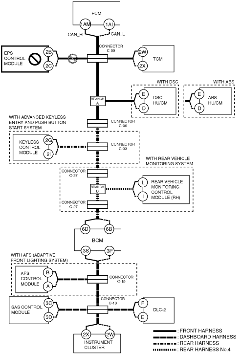
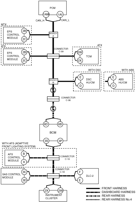
am6zzw00006608
|
Inspection item
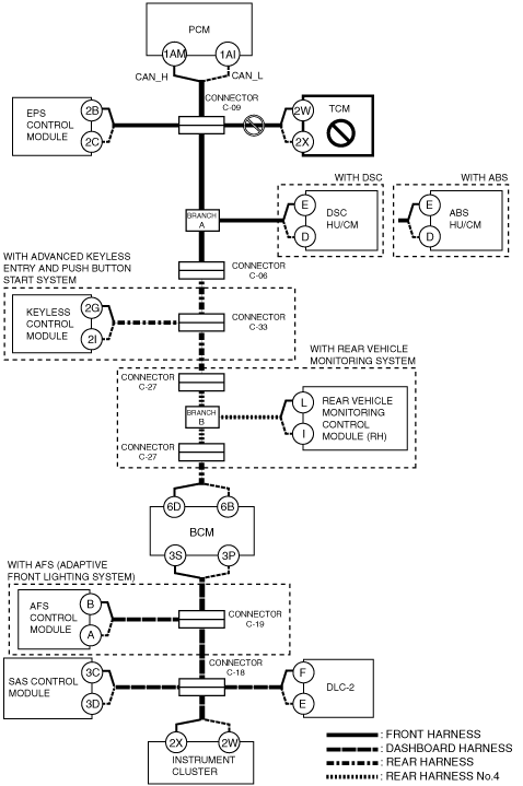
B
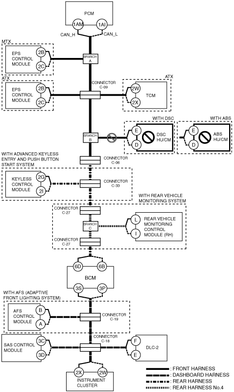
ATX
System wiring diagram
am6zzw00006611
|
MTX
System wiring diagram
am6zzw00006609
|
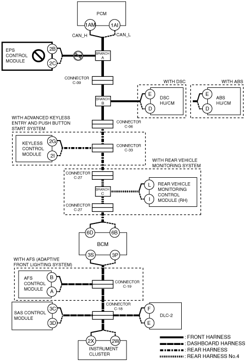
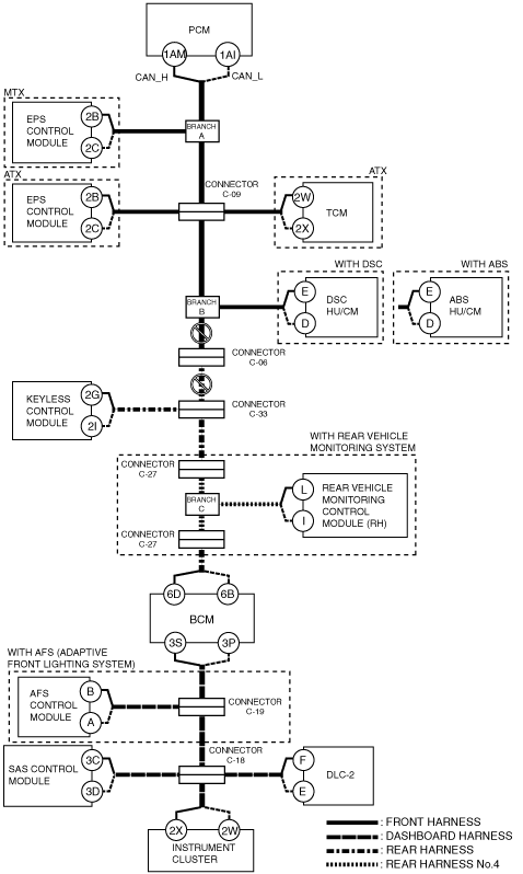
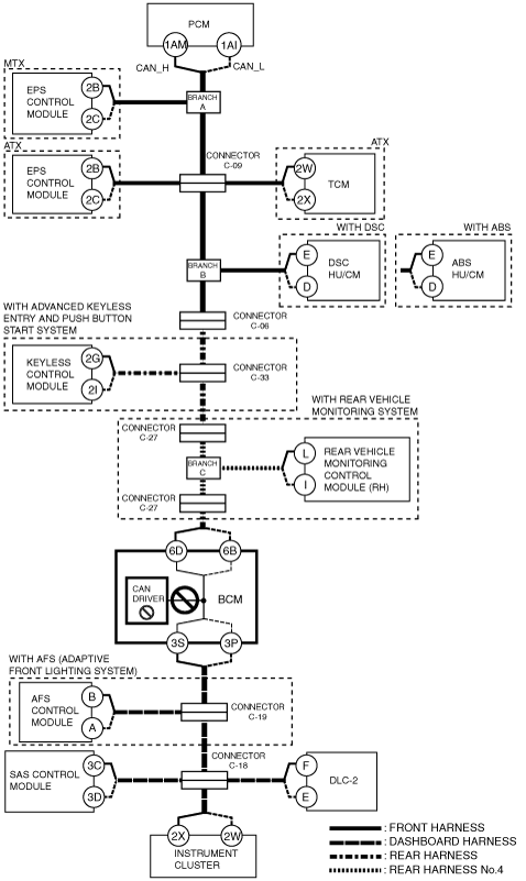
C
Possible cause
System wiring diagram
am6zzw00006610
|
Inspection item
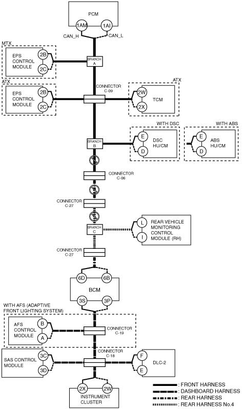
D
Possible cause
System wiring diagram
am6zzw00006612
|
Inspection item
E
Possible cause
System wiring diagram
am6zzw00006613
|
Inspection item
F
Possible cause
System wiring diagram
am6zzw00006614
|
Inspection item
G
With advanced keyless entry and push button start system
System wiring diagram
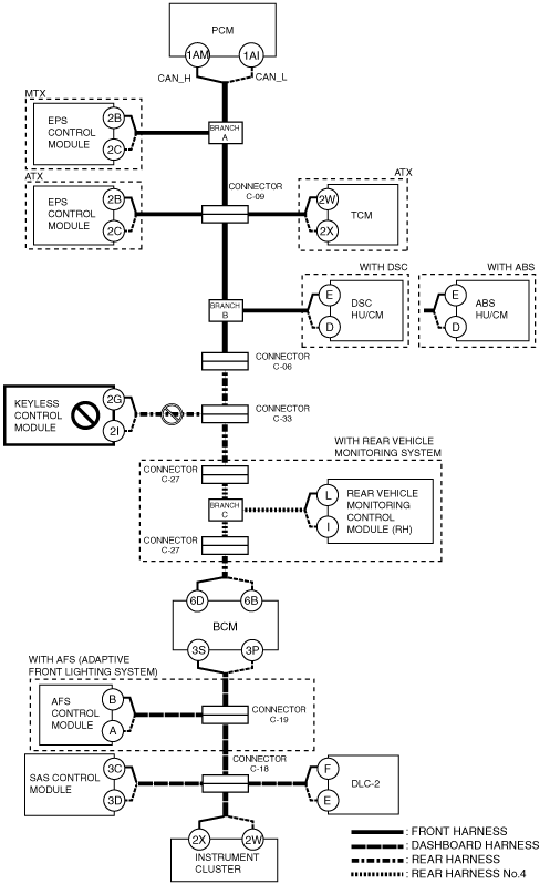
am6zzw00006616
|
Without advanced keyless entry and push button start system
System wiring diagram
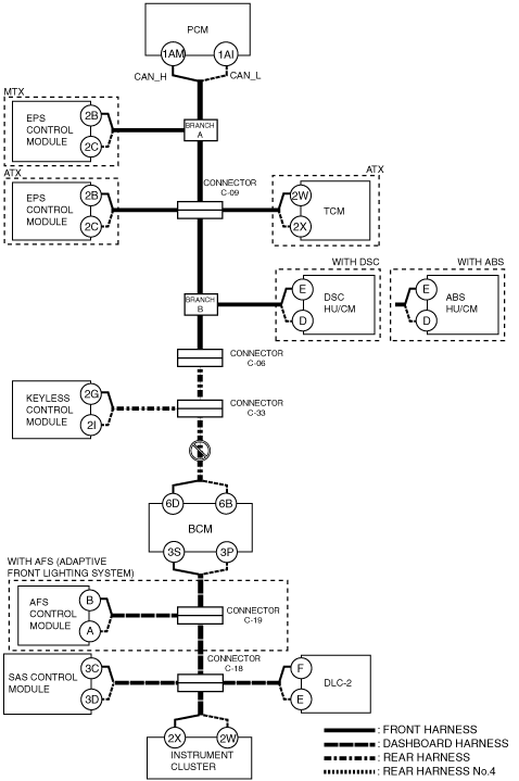
am6zzw00006620
|
Without advanced keyless entry and push button start system and rear vehicle monitoring system
System wiring diagram
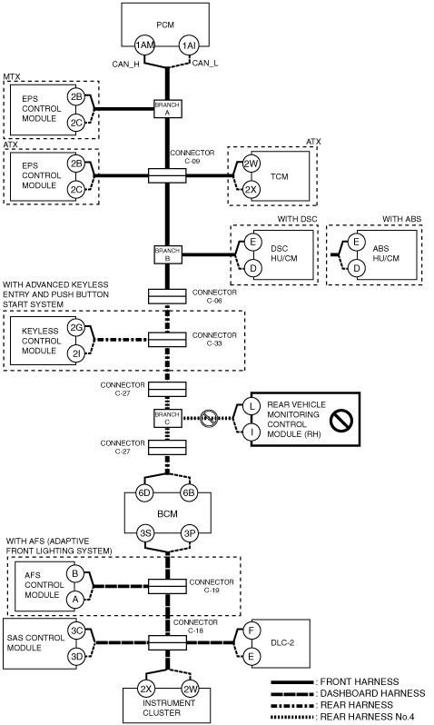
am6zzw00006623
|
H
Possible cause
System wiring diagram
am6zzw00006617
|
Inspection item
I
With rear vehicle monitoring system
System wiring diagram
am6zzw00006618
|
Without rear vehicle monitoring system
System wiring diagram
am6zzw00006622
|
J
Possible cause
System wiring diagram
am6zzw00006619
|
Inspection item
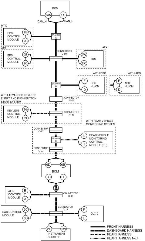
K
Possible cause
System wiring diagram
am6zzw00006621
|
Inspection item
L
Possible cause
System wiring diagram
am6zzw00006624
|
Inspection item
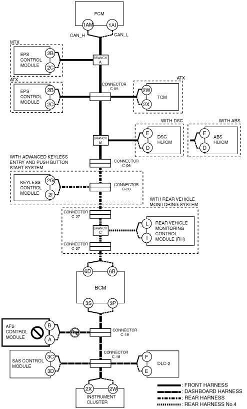
M
With AFS system
System wiring diagram
am6zzw00006625
|
Without AFS system
System wiring diagram
am6zzw00006628
|
N
Possible cause
System wiring diagram
am6zzw00006626
|
Inspection item
O
Possible cause
System wiring diagram
am6zzw00006627
|
Inspection item
P
Possible cause
System wiring diagram
am6zzw00006629
|
Inspection item
Q
Possible cause
System wiring diagram
am6zzw00006630
|
Inspection item