 |
am6zzw00006582
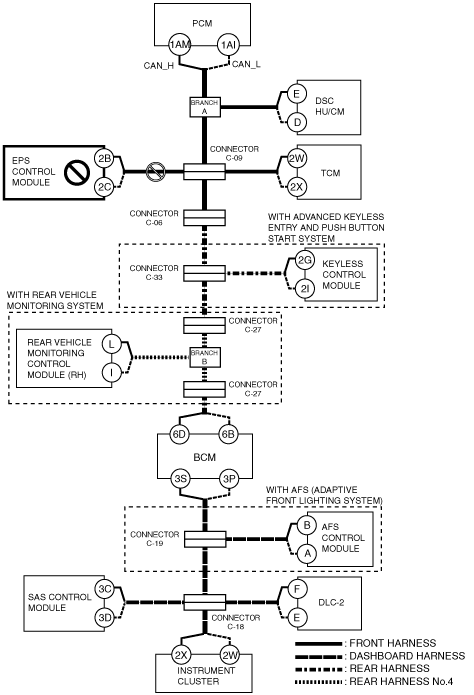
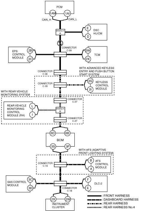
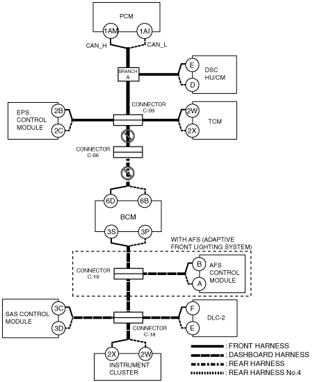
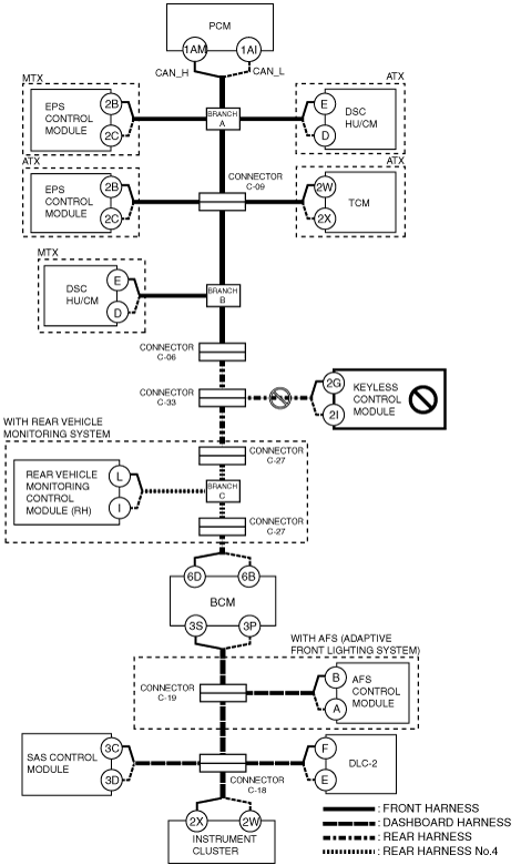
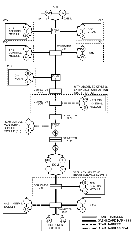
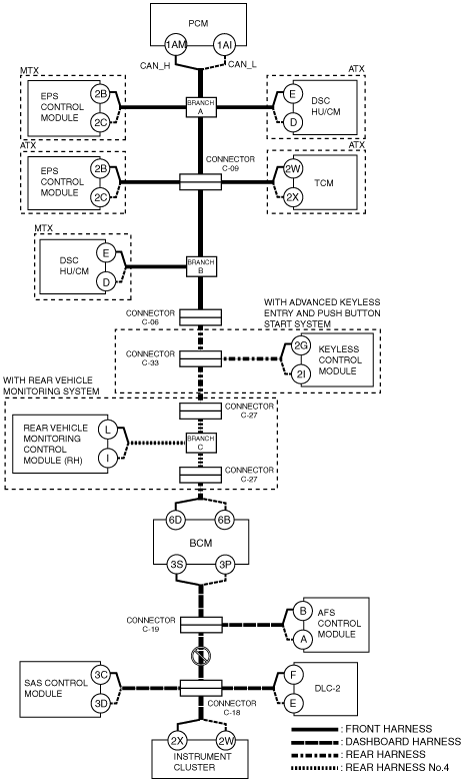
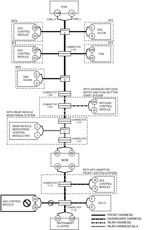
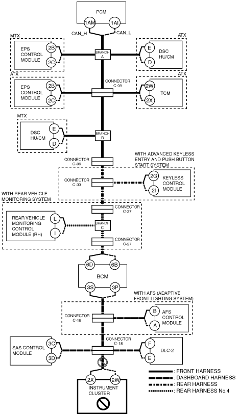
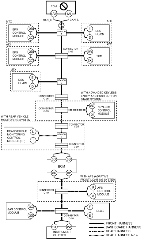
DETERMINING MALFUNCTIONING PART (HS-CAN) [MULTIPLEX COMMUNICATION SYSTEM (R.H.D. (MZR 2.0 DISI))]
id0902m1846700
1. Verify the CAN system-related module DTCs and the failed module using the (M-MDS).
2. Look for a DTC display pattern and failed module display pattern in tandem which match.
3. Refer to the matching tandem diagnostic results (A to R) and inspect the possible cause and inspection item.
4. Perform the DTC inspection after the repair procedure.
DTC Output Pattern and Malfunctioning Part
|
M-MDS display |
DTC display pattern |
||||||||||||||||||
|---|---|---|---|---|---|---|---|---|---|---|---|---|---|---|---|---|---|---|---|
|
DTC output module |
DTC |
||||||||||||||||||
|
PCM
(PCM)
|
U0101:00
|
|
|
|
|
|
×
|
|
|
|
|
|
|
|
|
|
|
|
|
|
U0121:00
|
|
|
×
|
|
|
|
|
|
|
|
|
|
|
|
|
|
|
|
|
|
U0131:00
|
|
×
|
|
|
|
|
|
|
|
|
|
|
|
|
|
|
|
|
|
|
U0140:00
|
|
|
|
|
|
|
|
|
|
|
|
|
×
|
|
|
|
|
|
|
|
U0155:00
|
|
|
|
|
|
|
|
|
|
|
|
|
|
|
|
|
|
×
|
|
|
ABS
(DSC HU/CM)
|
U0100:00
|
×
|
|
|
×
|
|
|
|
|
|
|
|
|
|
|
|
|
|
|
|
U0101:00
|
|
|
|
|
|
×
|
|
|
|
|
|
|
|
|
|
|
|
|
|
|
U0140:00
|
|
|
|
|
|
|
|
|
|
|
|
|
×
|
|
|
|
|
|
|
|
U0155:00
|
|
|
|
|
|
|
|
|
|
|
|
|
|
|
|
|
|
×
|
|
|
U0214:00
|
|
|
|
|
|
|
|
|
×
|
|
|
|
|
|
|
|
|
|
|
|
U0401:00
|
-
|
|
|
-
|
|
|
|
|
|
|
|
|
|
|
|
|
|
|
|
|
U0401:68
|
-
|
|
|
-
|
|
|
|
|
|
|
|
|
|
|
|
|
|
|
|
|
U0402:00
|
-*5
|
|
|
-
|
|
-
|
|
|
|
|
|
|
|
|
|
|
|
|
|
|
TCM*1
(TCM)
|
U0100:00
|
×
|
|
|
|
×
|
|
|
|
|
|
|
|
|
|
|
|
|
|
|
U0121:00
|
|
|
×
|
|
×
|
|
|
|
|
|
|
|
|
|
|
|
|
|
|
|
U0401:00
|
-
|
|
|
|
-
|
|
|
|
|
|
|
|
|
|
|
|
|
|
|
|
U0415:00
|
|
|
-
|
|
-
|
|
|
|
|
|
|
|
|
|
|
|
|
|
|
|
EPS
(EPS control module)
|
U0100:00
|
×
|
|
|
|
×
|
|
|
|
|
|
|
|
|
|
|
|
|
|
|
U0300:00
|
-
|
|
|
|
-
|
|
|
|
|
|
|
|
|
|
|
|
|
|
|
|
U0401:00
|
-
|
|
|
|
-
|
|
|
|
|
|
|
|
|
|
|
|
|
|
|
|
U2100:00
|
-
|
|
|
|
-
|
|
|
|
|
|
|
|
|
|
|
|
|
|
|
|
U3000:85
|
-
|
|
|
|
-
|
|
|
|
|
|
|
|
|
|
|
|
|
|
|
|
RKE*2
(Keyless control module)
|
U0100:00
|
×
|
|
|
×
|
×
|
|
×
|
×
|
|
|
|
|
|
|
|
|
|
|
|
U0101:00
|
|
|
|
|
|
×
|
×
|
|
|
|
|
|
|
|
|
|
|
|
|
|
U0121:00
|
|
|
×
|
|
×
|
|
×
|
×
|
|
|
|
|
|
|
|
|
|
|
|
|
RVM*3
(Rear vehicle monitoring control module (RH))
|
U0100:00
|
×
|
|
|
×
|
×
|
|
×
|
×
|
|
×
|
|
|
|
|
|
|
|
|
|
U0101:00
|
|
|
|
|
|
×
|
×
|
|
|
×
|
|
|
|
|
|
|
|
|
|
|
U0121:00
|
|
|
×
|
|
×
|
|
×
|
×
|
|
×
|
|
|
|
|
|
|
|
|
|
|
U0140:00
|
|
|
|
|
|
|
|
|
|
|
|
|
×
|
|
|
|
|
|
|
|
U0155:00
|
|
|
|
|
|
|
|
|
|
|
|
|
|
|
|
|
|
×
|
|
|
U0401:68
|
-
|
|
|
-
|
-
|
|
-
|
-
|
|
-
|
|
|
|
|
|
|
|
|
|
|
U0402:68
|
|
|
|
|
|
-
|
-
|
|
|
-
|
|
|
|
|
|
|
|
|
|
|
U0415:68
|
|
|
-
|
|
|
|
-
|
-
|
|
-
|
|
|
|
|
|
|
|
|
|
|
BCM/GEM
(BCM)
|
U0100:00
|
×
|
|
|
×
|
×
|
|
×
|
×
|
|
×
|
|
×
|
|
|
|
|
|
|
|
U0101:00
|
|
|
|
|
|
×
|
×
|
|
|
×
|
|
×
|
|
|
|
|
|
|
|
|
U0121:00
|
|
|
×
|
|
×
|
|
×
|
×
|
|
×
|
|
×
|
|
|
|
|
|
|
|
|
U0151:00
|
|
|
|
|
|
|
|
|
|
|
|
|
|
|
|
|
×
|
|
|
|
U0214:00
|
|
|
|
|
|
|
|
|
×
|
×
|
|
×
|
|
|
|
|
|
|
|
|
U0401:68
|
-
|
|
|
-
|
-
|
|
-
|
-
|
|
-
|
|
-
|
|
|
|
|
|
|
|
|
U0402:68
|
|
|
|
|
|
-
|
-
|
|
|
-
|
|
-
|
|
|
|
|
|
|
|
|
AFS*4
(AFS control module)
|
U0100:00
|
×
|
|
|
×
|
×
|
|
×
|
×
|
|
×
|
|
×
|
|
×
|
|
|
|
|
|
U0140:00
|
|
|
|
|
|
|
|
|
|
|
|
|
×
|
×
|
|
|
|
|
|
|
U0155:00
|
|
|
|
|
|
|
|
|
|
|
|
|
|
|
|
|
|
×
|
|
|
U0401:00
|
-
|
|
|
-
|
-
|
|
-
|
-
|
|
-
|
|
-
|
|
-
|
|
|
|
|
|
|
U0422:00
|
|
|
|
|
|
|
|
|
|
|
|
|
-
|
-
|
|
|
|
|
|
|
RCM
(SAS control module)
|
U0155:00
|
|
|
|
|
|
|
|
|
|
|
|
|
|
|
|
|
|
×
|
|
IC
(Instrument cluster)
|
U0100:00
|
×
|
|
|
×
|
×
|
|
×
|
×
|
|
×
|
|
×
|
|
×
|
|
×
|
|
|
|
U0100:87
|
-
|
|
|
-
|
-
|
|
-
|
-
|
|
-
|
|
-
|
|
-
|
|
-
|
|
|
|
|
U0101:00
|
|
|
|
|
|
×
|
×
|
|
|
×
|
|
×
|
|
×
|
|
×
|
|
|
|
|
U0121:00
|
|
|
×
|
|
×
|
|
×
|
×
|
|
×
|
|
×
|
|
×
|
|
×
|
|
|
|
|
U0140:00
|
|
|
|
|
|
|
|
|
|
|
|
|
×
|
×
|
|
×
|
|
|
|
|
U0151:00
|
|
|
|
|
|
|
|
|
|
|
|
|
|
|
|
|
×
|
|
|
|
U0182:00
|
|
|
|
|
|
|
|
|
|
|
|
|
|
|
×
|
×
|
|
|
|
|
U0214:00
|
|
|
|
|
|
|
|
|
×
|
×
|
|
×
|
|
×
|
|
×
|
|
|
|
|
U0232:00
|
|
|
|
|
|
|
|
|
|
|
×
|
×
|
|
×
|
|
×
|
|
|
|
|
U0401:68
|
-
|
|
|
-
|
-
|
|
-
|
-
|
|
-
|
|
-
|
|
-
|
|
-
|
|
|
|
|
U0401:92
|
-
|
|
|
-
|
-
|
|
-
|
-
|
|
-
|
|
-
|
|
-
|
|
-
|
|
|
|
|
U0402:68
|
|
|
|
|
|
-
|
-
|
|
|
-
|
|
-
|
|
-
|
|
-
|
|
|
|
|
U0402:92
|
|
|
|
|
|
-
|
-
|
|
|
-
|
|
-
|
|
-
|
|
-
|
|
|
|
|
U0415:68
|
|
|
-
|
|
-
|
|
-
|
-
|
|
-
|
|
-
|
|
-
|
|
-
|
|
|
|
|
U0415:92
|
|
|
-
|
|
-
|
|
-
|
-
|
|
-
|
|
-
|
|
-
|
|
-
|
|
|
|
|
U0452:92
|
|
|
|
|
|
|
|
|
|
|
|
|
|
|
|
|
-
|
|
|
|
U0483:68
|
|
|
|
|
|
|
|
|
|
|
|
|
|
|
-
|
-
|
|
|
|
|
U0483:92
|
|
|
|
|
|
|
|
|
|
|
|
|
|
|
-
|
-
|
|
|
|
|
U0515:68
|
|
|
|
|
|
|
|
|
-
|
-
|
|
-
|
|
-
|
|
-
|
|
|
|
|
U0515:92
|
|
|
|
|
|
|
|
|
-
|
-
|
|
-
|
|
-
|
|
-
|
|
|
|
|
U0533:68
|
|
|
|
|
|
|
|
|
|
|
-
|
-
|
|
-
|
|
-
|
|
|
|
|
U2005:86
|
-
|
|
|
-
|
-
|
|
-
|
-
|
|
-
|
|
-
|
|
-
|
|
-
|
|
|
|
|
M-MDS display module
|
“Fail” display pattern
|
||||||||||||||||||
|
PCM
|
×
|
|
|
×
|
×
|
|
×
|
×
|
|
×
|
|
×
|
|
×
|
|
×
|
|
|
|
|
ABS
|
|
|
×
|
|
×
|
|
×
|
×
|
|
×
|
|
×
|
|
×
|
|
×
|
|
|
|
|
TCM*1
|
|
|
|
|
|
×
|
×
|
|
|
×
|
|
×
|
|
×
|
|
×
|
|
|
|
|
EPS
|
|
×
|
|
×
|
|
|
×
|
×
|
|
×
|
|
×
|
|
×
|
|
×
|
|
|
|
|
RKE*2
|
|
|
|
|
|
|
|
|
×
|
×
|
|
×
|
|
×
|
|
×
|
|
|
|
|
RVM*3
|
|
|
|
|
|
|
|
|
|
|
×
|
×
|
|
×
|
|
×
|
|
|
|
|
BCM/GEM
|
|
|
|
|
|
|
|
|
|
|
|
|
×
|
×
|
|
×
|
|
|
|
|
AFS*4
|
|
|
|
|
|
|
|
|
|
|
|
|
|
|
×
|
×
|
|
|
|
|
RCM
|
|
|
|
|
|
|
|
|
|
|
|
|
|
|
|
|
×
|
|
|
|
IC
|
|
|
|
|
|
|
|
|
|
|
|
|
|
|
|
|
|
×
|
|
|
Item
|
Diagnostic result
|
||||||||||||||||||
|
Possible cause and inspection item
|
A
|
B
|
C
|
D
|
E
|
F
|
G
|
H
|
I
|
J
|
K
|
L
|
M
|
N
|
O
|
P
|
Q
|
R
|
|
|
Reference page
|
|||||||||||||||||||
A
Possible cause
System wiring diagram
am6zzw00006582
|
Inspection item
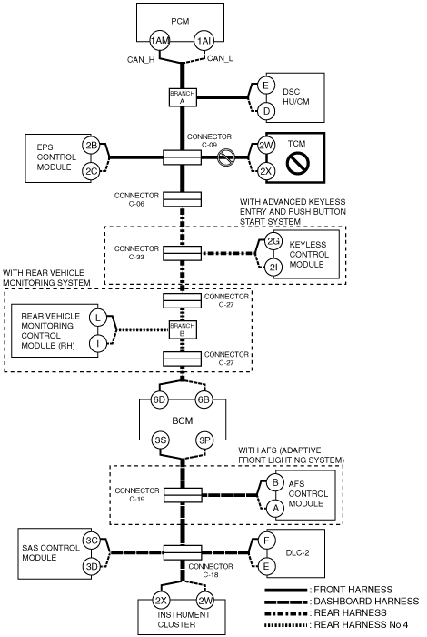
B
ATX
System wiring diagram
am6zzw00006586
|
MTX
System wiring diagram
am6zzw00006583
|
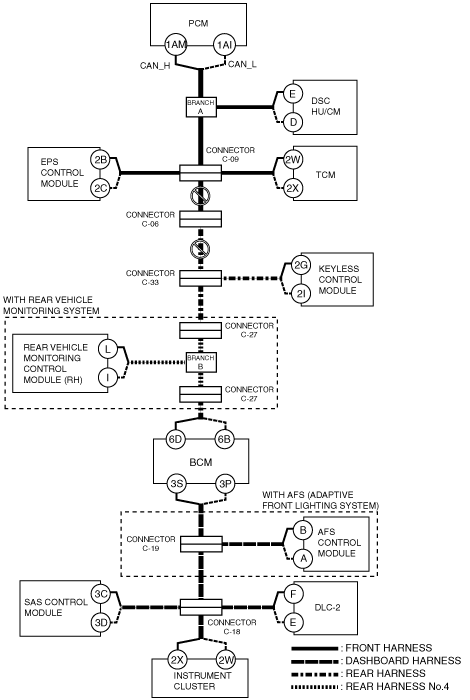
C
ATX
System wiring diagram
am6zzw00006584
|
MTX
System wiring diagram
am6zzw00006589
|
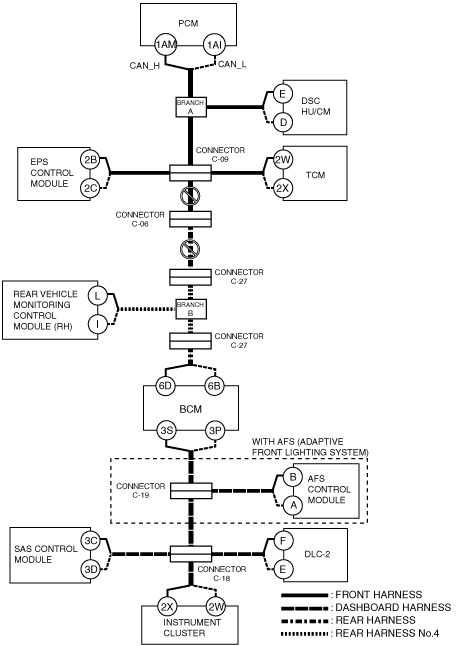
D
Possible cause
System wiring diagram
am6zzw00007167
|
Inspection item
E
Possible cause
System wiring diagram
am6zzw00007168
|
Inspection item
F
Possible cause
System wiring diagram
am6zzw00006587
|
Inspection item
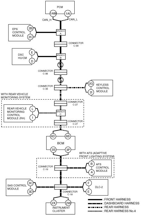
G
With advanced keyless and push button start system
System wiring diagram
am6zzw00007169
|
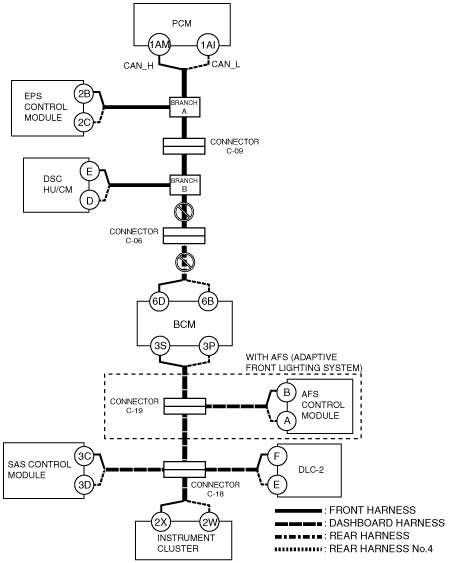
Without advanced keyless and push button start system
System wiring diagram
am6zzw00007170
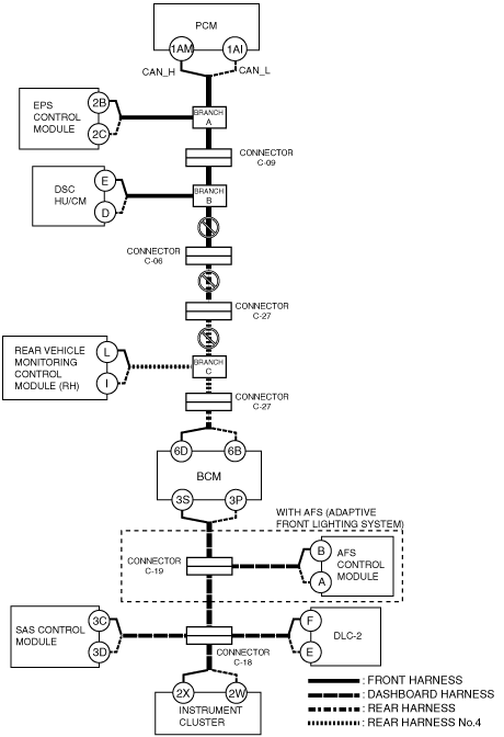
|
Without advanced keyless and push button start system and rear vehicle monitoring system
System wiring diagram
am6zzw00007171
|
H
With advanced keyless and push button start system
System wiring diagram
am6zzw00006590
|
Without advanced keyless and push button start system
System wiring diagram
am6zzw00006593
|
Without advanced keyless and push button start system and rear vehicle monitoring system
System wiring diagram
am6zzw00006597
|
I
Possible cause
System wiring diagram
am6zzw00006591
|
Inspection item
J
With rear vehicle monitoring system
System wiring diagram
am6zzw00006592
|
Without rear vehicle monitoring system
System wiring diagram
am6zzw00006596
|
K
Possible cause
System wiring diagram
am6zzw00006594
|
Inspection item
L
Possible cause
System wiring diagram
am6zzw00006595
|
Inspection item
M
Possible cause
System wiring diagram
am6zzw00006598
|
Inspection item
N
With AFS system
System wiring diagram
am6zzw00006599
|
Without AFS system
System wiring diagram
am6zzw00006602
|
O
Possible cause
System wiring diagram
am6zzw00006600
|
Inspection item
P
Possible cause
System wiring diagram
am6zzw00006601
|
Inspection item
Q
Possible cause
System wiring diagram
am6zzw00006603
|
Inspection item
R
Possible cause
System wiring diagram
am6zzw00006604
|
Inspection item