 |
am6zzw00004740
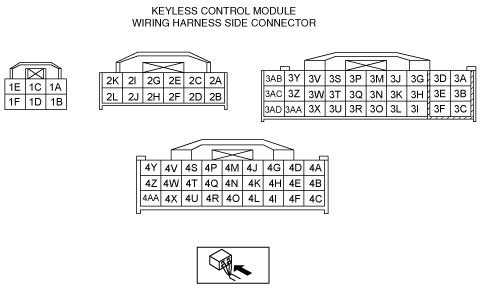
KEYLESS CONTROL MODULE INSPECTION [ADVANCED KEYLESS ENTRY AND PUSH BUTTON START SYSTEM]
id0914004385z3
1. Remove the front scuff plate. (See FRONT SCUFF PLATE REMOVAL/INSTALLATION.)
2. Remove the front side trim. (See FRONT SIDE TRIM REMOVAL/INSTALLATION.)
3. Measure the voltage according to the terminal voltage table.
Terminal Voltage Table (Reference)
am6zzw00004740
|
|
Terminal |
Signal name |
Connected to |
Measurement condition |
Voltage (V) |
Inspection item (s) |
||
|---|---|---|---|---|---|---|---|
|
1A
|
Steering lock unit ground
|
Steering lock unit
|
During steering lock unit operation
|
1.0 or less
|
Steering lock unit
|
||
|
Other
|
Approx. 3.0
|
||||||
|
1B
|
Power supply
|
STEERING LOCK 10 A fuse
|
Under any condition
|
B+
|
STEERING LOCK 10 A fuse
Battery
|
||
|
1C
|
Power supply
|
Steering lock unit
|
Steering lock unit During lock/unlock control
|
B+
|
Steering lock unit
|
||
|
Other
|
1.0 or less
|
||||||
|
1D
|
Power supply
|
BCM
|
Under any condition
|
B+
|
ROOM 15 A fuse
Battery
BCM
|
||
|
1E
|
Power supply
|
EGI 5 A fuse
|
Under any condition
|
B+
|
EGI 5 A fuse
Battery
|
||
|
1F
|
GND
|
Body ground
|
Under any condition
|
1.0 or less
|
Body ground
|
||
|
2A
|
Power supply
|
MIRROR 5 A fuse
|
Switch the ignition to ACC
|
B+
|
ACC relay
MIRROR 5 A fuse
Battery
|
||
|
Switch the ignition to off
|
1.0 or less
|
||||||
|
2B
|
Rx-PATS
|
Coil antenna
|
Communication lines, cannot be determined by voltage only (B+ when not communicating)
|
B+
|
Coil antenna
|
||
|
2C
|
Power supply
|
ENGINE IG 15 A fuse
|
Switch the ignition to ON
|
B+
|
IG1 relay
ENGINE IG 15 A fuse
Battery
|
||
|
Switch the ignition to ACC or off
|
1.0 or less
|
||||||
|
2D
|
Tx-PATS
|
Coil antenna
|
Communication lines, cannot be determined by voltage only (B+ when not communicating)
|
B+
|
Coil antenna
|
||
|
2F
|
BCM communication
|
BCM
|
Communication lines, cannot be determined by voltage only (B+ when not communicating)
|
B+
|
BCM
|
||
|
2G
|
HS-CAN+
|
-
|
Terminal used for communication therefore determination based on terminal voltage inspection not possible.
|
||||
|
2H
|
Keyless entry communication
|
Keyless receiver
|
Terminal used for communication therefore determination based on terminal voltage inspection not possible.
|
||||
|
2I
|
HS-CAN-
|
-
|
Terminal used for communication therefore determination based on terminal voltage inspection not possible.
|
||||
|
2J
|
Push button start
|
Push button start
|
Push button start is pushed
|
1.0 or less
|
Push button start
|
||
|
Push button start is not pushed
|
B+
|
||||||
|
2K
|
Push button start
|
Push button start
|
Push button start is pushed
|
1.0 or less
|
Push button start
|
||
|
Push button start is not pushed
|
B+
|
||||||
|
2L
|
Steering lock unit communication
|
Steering lock unit
|
Terminal used for communication therefore determination based on terminal voltage inspection not possible.
|
||||
|
3B*1
|
Clutch pedal position switch
|
Clutch pedal position switch
|
Clutch pedal is depressed
|
1.0 or less
|
Clutch pedal position switch
|
||
|
Clutch pedal is not depressed
|
B+
|
||||||
|
3C
|
Keyless antenna (exterior, rear)
|
Keyless antenna (exterior, rear)
|
Terminal used for communication therefore determination based on terminal voltage inspection not possible.
|
||||
|
3D
|
Liftgate (WGN)
|
Request switch (Liftgate) (WGN)
|
Liftgate request switch is pressed
|
1.0 or less
|
Request switch (Liftgate) (WGN)
|
||
|
Liftgate request switch is released
|
B+
|
||||||
|
3E
|
Brake switch
|
Brake switch
|
Brake pedal is depressed
|
Wave pattern (See Pattern 1.)
|
Brake switch
|
||
|
Brake pedal is not depressed
|
1.0 or less
|
||||||
|
3F
|
Keyless antenna (LF)
|
Keyless antenna (LF)
|
Terminal used for communication therefore determination based on terminal voltage inspection not possible.
|
||||
|
3G
|
Trunk lid unlatch input (4SD)Liftgate unlatch input (5HB, WGN)
|
Trunk lid opener switch (4SD)Liftgate opener switch (5HB, WGN)
|
Trunk lid/liftgate opener switch is pressed
|
3.0
|
Trunk lid opener switch (4SD)Liftgate opener switch (5HB, WGN)
|
||
|
Trunk lid/liftgate opener switch is released
|
4.7
|
||||||
|
3H
|
Unlock input
|
Touch sensor (RF)
|
Terminal used for communication therefore determination based on terminal voltage inspection not possible.
|
||||
|
3I
|
Keyless antenna (interior, rear)
|
Keyless antenna (interior, rear)
|
Terminal used for communication therefore determination based on terminal voltage inspection not possible.
|
||||
|
3K
|
Keyless beeper power supply
|
Keyless beeper
|
Exterior keyless beeper sounds
|
5.0 or more
|
Keyless beeper
|
||
|
Other
|
1.0 or less
|
||||||
|
3L
|
Keyless antenna (interior, center)
|
Keyless antenna (interior, center)
|
Terminal used for communication therefore determination based on terminal voltage inspection not possible.
|
||||
|
3M*2
|
P position
|
Transaxle range switch
|
Shift position is P
|
Wave pattern (See Pattern 1.)
|
Transaxle range switch
|
||
|
Other
|
1.0 or less
|
||||||
|
3N
|
GND
|
Body ground
|
Under any condition
|
1.0 or less
|
Body ground
|
||
|
3O
|
Keyless antenna (RF)
|
Keyless antenna (RF)
|
Terminal used for communication therefore determination based on terminal voltage inspection not possible.
|
||||
|
3P
|
Lock input
|
Door lock-link switch (driver's door)
|
Driver's side door lock switch at LOCK
|
1.0 or less
|
Door lock-link switch
|
||
|
Driver's side door lock switch at UNLOCK
|
Wave pattern (See Pattern 2.)
|
||||||
|
3Q
|
Unlock input
|
Touch sensor (LF)
|
Terminal used for communication therefore determination based on terminal voltage inspection not possible.
|
||||
|
3R
|
Keyless antenna (interior, front)
|
Keyless antenna (interior, front)
|
Terminal used for communication therefore determination based on terminal voltage inspection not possible.
|
||||
|
3S
|
Brake switch
|
Brake switch
|
Brake pedal is depressed
|
B+
|
Brake switch
|
||
|
Brake pedal is not depressed
|
1.0 or less
|
||||||
|
3T*1
|
Neutral switch
|
Neutral switch
|
Shift lever is in neutral position
|
1.0 or less
|
Neutral switch
|
||
|
Shift lever is not in neutral position
|
Wave pattern (See Pattern 1.)
|
||||||
|
3U
|
Request switch (RF)
|
Request switch (RF)
|
Request switch is pressed
|
1.0 or less
|
Front outer handle (RF)
|
||
|
Request switch is released
|
B+
|
||||||
|
3X
|
Request switch (LF)
|
Request switch (LF)
|
Request switch is pressed
|
1.0 or less
|
Front outer handle (LF)
|
||
|
Request switch is released
|
B+
|
||||||
|
3Y
|
Keyless antenna (interior, center)
|
Keyless antenna (interior, center)
|
Terminal used for communication therefore determination based on terminal voltage inspection not possible.
|
||||
|
3Z
|
Keyless antenna (interior, rear)
|
Keyless antenna (interior, rear)
|
Terminal used for communication therefore determination based on terminal voltage inspection not possible.
|
||||
|
3AA
|
Keyless antenna (interior, front)
|
Keyless antenna (interior, front)
|
Terminal used for communication therefore determination based on terminal voltage inspection not possible.
|
||||
|
3AB
|
Keyless antenna (LF)
|
Keyless antenna (LF)
|
Terminal used for communication therefore determination based on terminal voltage inspection not possible.
|
||||
|
3AC
|
Keyless antenna (exterior, rear)
|
Keyless antenna (exterior, rear)
|
Terminal used for communication therefore determination based on terminal voltage inspection not possible.
|
||||
|
3AD
|
Keyless antenna (RF)
|
Keyless antenna (RF)
|
Terminal used for communication therefore determination based on terminal voltage inspection not possible.
|
||||
|
4A
|
Steering lock unit unlock
|
Steering lock unit
|
Steering lock unit Unlocked condition
|
1.0 or less
|
Steering lock unit
|
||
|
Steering lock unit Locked condition
|
Wave pattern (See Pattern 2.)
|
||||||
|
4B
|
Starter relay
|
Starter relay
|
Cranking
|
B+
|
Starter relay
|
||
|
Other (Remove the starter relay)
|
1.0 or less
|
||||||
|
4E
|
IG 1 relay control
|
IG 1 Relay
|
Switch the ignition to ON
|
B+
|
IG 1 Relay
|
||
|
Switch the ignition to off or ACC
|
1.0 or less
|
||||||
|
4F
|
ACC relay control
|
ACC Relay
|
Switch the ignition to ACC
|
B+
|
ACC Relay
|
||
|
Switch the ignition to off
|
1.0 or less
|
||||||
|
4H
|
IG 2 relay control
|
IG 2 Relay
|
Switch the ignition to ON
|
B+
|
IG 2 Relay
|
||
|
Switch the ignition to off or ACC
|
1.0 or less
|
||||||
|
4J
|
Push button illumination (ACC)
|
Push button start
|
In the case of ACC
|
1.0 or less
|
Push button start
|
||
|
Case except the ACC
|
B+
|
||||||
|
4K
|
Starter interlock switch
(MTX)
|
Starter interlock switch
|
Switch the ignition to off
|
Clutch pedal is not depressed
|
1.0 or less
|
Starter interlock switch
|
|
|
Clutch pedal is depressed
|
4.0 or more
|
||||||
|
Transaxle range switch
(ATX)
|
Transaxle range switch
|
Shift position is not P or N range
|
1.0 or less
|
Transaxle range switch
|
|||
|
Shift position is P or N range
|
4.0 or more
|
||||||
|
4L
|
GND
|
Body ground
|
Under any condition
|
1.0 or less
|
Body ground
|
||
|
4Q
|
Power supply
|
Coil antenna
|
Communication lines, cannot be determined by voltage only (B+ when not communicating)
|
B+
|
Coil antenna
Push button start
|
||
|
4R
|
Ring illumination (immobilizer system)
|
Coil antenna
|
Terminal used for communication therefore determination based on terminal voltage inspection not possible.
|
Coil antenna
|
|||
|
4S
|
Power supply
|
Combined sensor
|
Until steering lock unit locks after switch the ignition to off
|
B+
|
Combined sensor
BCM
ABS/DCS HU/CM
|
||
|
Steering lock unit locks after switch the ignition to off
|
1.0 or less
|
||||||
|
4T
|
Push button illumination (Umber)
|
Push button start
|
System is malfunctioning
|
1.0 or less
|
Push button start
|
||
|
Other
|
B+
|
||||||
|
4U
|
TNS
|
Auto light/wiper control module
|
TNS ON
|
B+
|
Auto light/wiper control module
|
||
|
TNS OFF
|
1.0 or less
|
||||||
|
4W
|
Push button illumination (ON)
|
Push button start
|
In the case of ON
|
1.0 or less
|
Push button start
|
||
|
Case except the ON
|
B+
|
||||||
|
4X
|
Power supply
|
WIPER 20 A fuse
|
Switch the ignition to ON
|
B+
|
IG 2 Relay
WIPER 20 A fuse
Battery
|
||
|
Switch the ignition to off or ACC
|
1.0 or less
|
||||||
|
4Y
|
Push button illumination (green)
|
Push button start
|
Engine start is available
|
1.0 or less
|
Push button start
|
||
|
Other
|
B+
|
||||||
|
4AA
|
Starter monitor
|
Starter relay
|
Switch the ignition to off
|
Clutch pedal is not depressed (MTX)
|
1.0 or less
|
Starter relay
|
|
|
Shift position is not P or N range (ATX)
|
|||||||
|
Clutch pedal is depressed (MTX)
|
4.0 or more
|
||||||
|
Shift position is P or N range (ATX)
|
|||||||
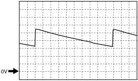
Generated pulse (reference)
Pattern 1
am6zzw00005453
|
Pattern 2
aatjjw00004591
|