 |
am2zzw00001852
INTRUDER SENSOR INSPECTION
id091400819400
1. Disconnect the negative battery cable.
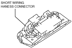
2. Remove the intruder sensor cover. (See INTRUDER SENSOR COVER REMOVAL/INSTALLATION.)
3. Measure the intruder sensor terminal voltage using the short wiring harness connector in the position shown in the figure.
am2zzw00001852
|
Terminal Voltage Table (Reference)
am6zzw00006325
|
|
Terminal |
Signal name |
Connected to |
Measurement condition |
Voltage (V) |
Inspection item (s) |
|---|---|---|---|---|---|
|
B
|
GND
|
Body ground
|
Under any condition
|
1.0 or less
|
Ground
|
|
C
|
DATA
|
BCM
|
Terminal used for communication therefore determination based on terminal voltage inspection not possible.
|
||
|
D
|
Power supply
|
ROOM 15 A fuse
|
Under any condition
|
B+
|
ROOM 15 A fuse
|
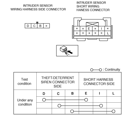
Continuity Inspection Of Short Wiring Harness Connector
1. Verify that the continuity between the short wiring harness connector terminals is as indicated in the table.
am6zzw00002654
|