AFS (ADAPTIVE FRONT LIGHTING SYSTEM) OPERATION
id091800692700
• The auto leveling function operates while the running lights are turned on, however, the swivel function does not operate.
Swivel Function
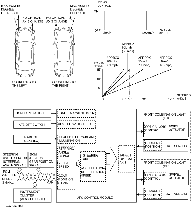
• The swivel function is controlled by the AFS control module.
• The AFS control module constantly calculates the amount of swivel actuator control based on the steering operation angle signal sent from the steering angle sensor and the vehicle speed signal sent from the PCM when the ignition is switched ON.
• If the following operation conditions are met, the AFS control module controls the swivel actuator based on the calculated amount of control, and adjusts the headlight optical axis.
Operation condition
|
Item
|
Operation conditions
|
|
Initial Setting (swivel function)
|
After normal completion
|
|
Headlight (LO)
|
ON (illuminated)
|
|
AFS OFF switch
|
OFF (control status)
|
|
Gear position
|
Reverse gear position
|
|
Vehicle speed
|
Control startup: 2 km/h {1 mph} or more
|
|
Control stop: 2 km/h {1 mph} or less
|
• The maximum variation (swivel angle) of the optical axis of the headlight (LO) is 15 degrees for right and left.
• Changes in the headlight (low beam) optical axis (swivel angle) are controlled freely (non-step) based on the vehicle speed and the steering angle.
• The steering wheel angle amount changes according to the vehicle speed until reaching the maximum value of the swivel angle (15 degrees). Up to a certain vehicle speed (approx. 50 km/h {31 mph}), the steering wheel angle amount decreases until reaching the maximum value (15 degrees) of the swivel angle. After exceeding a certain vehicle speed (approx. 50 km/h {31 mph}), the steering wheel angle amount increases until reaching the maximum value (15 degrees) of the swivel angle unless there is an increase in vehicle speed.
• The swivel actuator activates the motor based on the signals from the AFS control module. Changes in the optical axis of the headlights are detected by the hall sensor and input to the AFS control module.
HEADLIGHT AUTO LEVELING SYSTEM FUNCTION
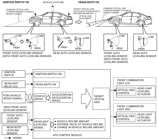
• The headlight auto leveling system is controlled by the AFS control module.
• The AFS control module constantly calculates the amount of vehicle inclination based on the vehicle height signal from the auto leveling sensor when the ignition is switched ON.
• The AFS control module calculates the acceleration and deceleration speed of the vehicle from the PCM after the ignition is switched ON.
• With the ignition switched ON and the headlights switched from off to on, the AFS control module calculates the target headlight optical axis based on an average of the calculated amount of vehicle inclination, and outputs the target headlight optical axis signal to the headlight leveling actuator.
• Based on the target headlight optical axis signal from the AFS control module, the headlight leveling actuator drives the motor until it reaches the target headlight optical axis level.
• The AFS control module controls the headlight optical axis in the following cases:
Headlights switched from off to on while vehicle is stopped
-
• Operation conditions
-
― Ignition switch ON
― Vehicle speed 0 km/h {0 mph}
― At point in time headlights are switched from off to on
-
• Operation
-
1. If the AFS control module detects a headlight on signal from the headlight relay (LO), it calculates the target headlight optical axis based on the amount of vehicle inclination calculated in the 1 s period directly prior to detecting the headlight on signal.
2. The AFS control module outputs the target headlight optical axis signal to the headlight leveling actuator.
3. The headlight leveling actuator calculates the amount of motor drive based on the target headlight optical axis signal from the AFS control module and drives the motor until the headlights reach the target headlight optical axis level.
After headlights are switched from off to on while vehicle is stopped, and vehicle height changes (rear passengers, load changes)
-
• Operation conditions
-
― Ignition switch ON
― Vehicle speed 0 km/h {0 mph}
― Headlights on
― At point where amount of vehicle inclination change exceeds threshold value
-
• Operation
-
1. The AFS control module monitors the amount of vehicle inclination for a 3 s period from the point that the amount of vehicle inclination change, resulting from rear passenger or load changes, exceeds the threshold value.
2. If the amount of vehicle inclination change during the 3 s period does not exceed the threshold value, the headlight optical axis is calculated based on the average amount of vehicle inclination in the final 1 s period.
3. The AFS control module outputs the target headlight optical axis signal to the headlight leveling actuator.
4. The headlight leveling actuator calculates the amount of motor drive based on the target headlight optical axis signal from the AFS control module and drives the motor until the headlights reach the target headlight optical axis level.
Headlights switched from off to on while vehicle in transit
-
• Operation conditions
-
― Ignition switch ON
― Vehicle speed 30 km/h {19 mph} or more and during travel at constant vehicle speed
― At point in time headlights switched from off to on
-
• Operation
-
1. The AFS control module records the average amount of vehicle inclination calculated at the point in time when the vehicle first begins to travel from a stopped condition and in the 1 s period after the vehicle is stopped.
2. If the AFS control module detects a headlight on signal from the headlight relay (LO) while the vehicle is traveling, it calculates the target headlight optical axis based on the average amount of vehicle inclination which was previously recorded.
3. The AFS control module outputs the target headlight optical axis signal to the headlight leveling actuator.
4. The headlight leveling actuator calculates the amount of motor drive based on the target headlight optical axis signal from the AFS control module and drives the motor until the headlights reach the target headlight optical axis level.
Amount of vehicle inclination changes as result of vehicle going from stopped condition to being driven
-
• Operation conditions
-
― Ignition switch ON
― Vehicle speed 30 km/h {19 mph} or more and during travel at constant vehicle speed
― At point in time headlights switched from off to on
― At point where amount of vehicle inclination change exceeds threshold value
-
• Operation
-
1. The AFS control module monitors the amount of vehicle inclination for a 3 s period from the point that the amount of vehicle inclination change, resulting from the vehicle going from a stopped condition to one of being driven, exceeds the threshold value.
2. If the amount of vehicle inclination change during the 3 s period does not exceed the threshold value, the headlight optical axis is calculated based on the average amount of vehicle inclination in the final 1 s period.
3. The AFS control module outputs the target headlight optical axis signal to the headlight leveling actuator.
4. The headlight leveling actuator calculates the amount of motor drive based on the target headlight optical axis signal from the AFS control module and drives the motor until the headlights reach the target headlight optical axis level.
Amount of vehicle inclination changes during vehicle travel
-
Note
-
• Control of the headlight optical axis during vehicle travel is performed one time during one period of travel.
-
• Operation conditions
-
― Ignition switch ON
― Vehicle speed 30 km/h {19 mph} or more and during travel at constant vehicle speed
― At point in time headlights switched from off to on
― At point where amount of vehicle inclination change exceeds threshold value
-
• Operation
-
1. The AFS control module monitors the amount of vehicle inclination for a 3 s period from the point that the amount of vehicle inclination change, resulting from the change in the amount of vehicle inclination during vehicle travel, exceeds the threshold value.
2. If the amount of vehicle inclination change during the 3 s period does not exceed the threshold value, the headlight optical axis is calculated based on the average amount of vehicle inclination in the final 1 s period.
3. The AFS control module outputs the target headlight optical axis signal to the headlight leveling actuator.
4. The headlight leveling actuator calculates the amount of motor drive based on the target headlight optical axis signal from the AFS control module and drives the motor until the headlights reach the target headlight optical axis level.