|
bc62zm00000075
TRANSAXLE ASSEMBLY
id051500170000
Step 1
1. Perform the primary shaft and secondary shaft preload adjustment and select a shim of the appropriate thickness. (See BEARING PRELOAD ADJUSTMENT.)
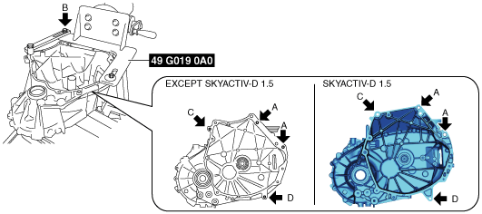
2. Assemble the SST (49 G019 0A0) to the SST (49 0107 680A).
bc62zm00000075
|
3. Assemble the clutch housing component to the SST.
bc62zm00000097
|
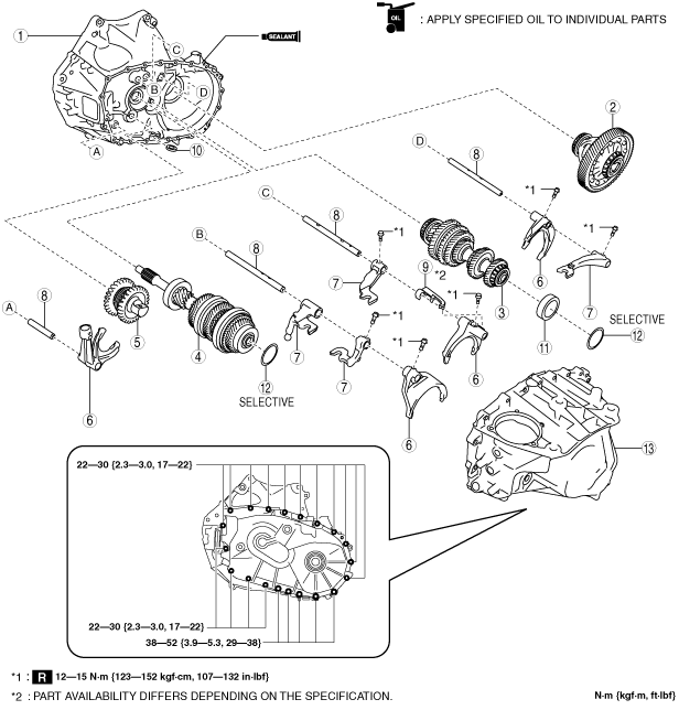
4. Assemble the MTX in the order shown in the figure.
bc62zm00000077
|
|
1
|
Clutch housing component
|
|
2
|
Differential
|
|
3
|
Secondary shaft component
|
|
4
|
Primary shaft component
|
|
5
|
Reverse idler gear component
|
|
6
|
Shift fork
|
|
7
|
Shift rod end
|
|
8
|
Shift rod
|
|
9
|
Oil path
|
|
10
|
Magnet
|
|
11
|
bearing outer race
|
|
12
|
shim
|
|
13
|
Transaxle case component
|
Secondary shaft component and primary shaft component assembly note
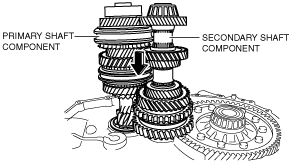
1. Assemble the secondary shaft component and primary shaft component to the clutch housing component as a single unit.
bc62zm00000078
|
2. Shake the assembled parts and assemble each one completely.
Reverse idler gear component assembly note
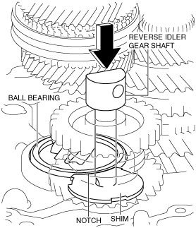
1. Pull the reverse idler gear shaft and position it to the location shown in the figure.
bc62zm00000079
|
2. Engage each gear while aligning the shim notch with the ball bearing of the primary shaft component.
3. Push the reverse idler gear shaft and assemble the reverse idler gear component.
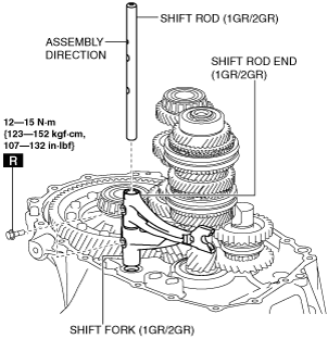
Shift fork, shift rod end, and shift rod assembly note
1. Assemble the shift fork (1GR/2GR), shift rod end (1GR/2GR), and shift rod (1GR/2GR) using the following procedure:
bc62zm00000080
|
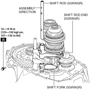
2. Assemble the shift fork (5GR/6GR), shift rod end (5GR/6GR), and shift rod (5GR/6GR) using the following procedure:
bc62zm00000081
|
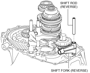
3. Assemble the shift fork (reverse) and shift rod (reverse) using the following procedure:
bc62zm00000082
|
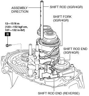
4. Assemble the shift fork (3GR/4GR), shift rod end (3GR/4GR), shift rod end (reverse), and shift rod (3GR/4GR) using the following procedure:
bc62zm00000083
|
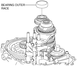
Bearing outer race, shim, Transaxle case component assembly note
1. Assemble the bearing outer race to the secondary shaft component.
bc62zm00000084
|
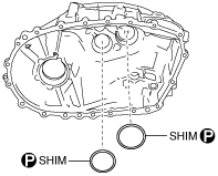
2. Assemble the shims.
bc62zm00000085
|
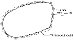
3. Apply silicone sealant to the transaxle case component as shown in the figure.
bc62zm00000086
|
4. Assemble the transaxle case component.
bc62zm00000087
|
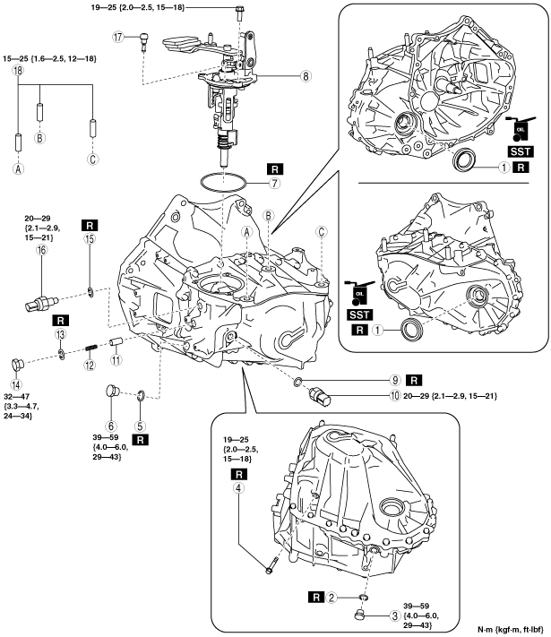
Step 2
1. Assemble the parts around the MTX in the order shown in the figure.
bc62zm00000088
|
|
1
|
Oil seal
(See Oil seal assembly note.)
|
|
2
|
Gasket
|
|
3
|
Drain plug
|
|
4
|
Reverse gear shaft anchor bolt
|
|
5
|
Gasket
|
|
6
|
Oil level plug
|
|
7
|
O-ring
|
|
8
|
Shift control module
|
|
9
|
Gasket
|
|
10
|
Back-up light switch
|
|
11
|
Detent ball pin
|
|
12
|
Spring
|
|
13
|
Gasket
|
|
14
|
Plug
|
|
15
|
Gasket
|
|
16
|
Neutral switch
|
|
17
|
Breather
|
|
18
|
Stud bolt
(See Stud bolt assembly note.)
|
Oil seal assembly note
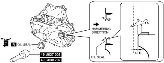
1. Assemble a new oil seal (LH) to the transaxle case using the SSTs.
bc62zm00000089
|
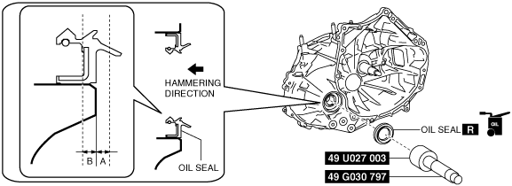
2. Assemble a new oil seal (RH) to the clutch housing using the SST. (2WD)
bc62zm00000090
|
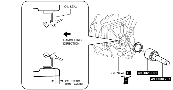
3. Assemble a new oil (RH) seal to the clutch housing using the SSTs. (4WD)
bc62zm00000091
|
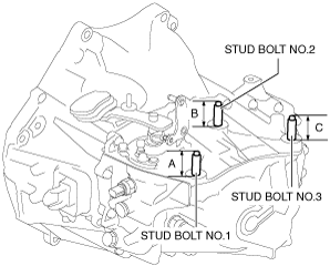
Stud bolt assembly note
1. Measure the projection amount of the stud bolts.
bc62zm00000098
|