 |
bfw4ua00000042
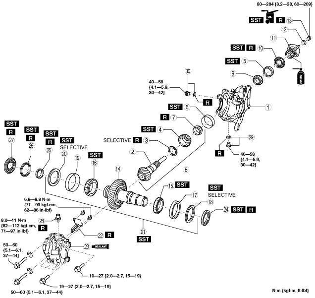
TRANSFER ASSEMBLY
id031600000300
bfw4ua00000042
|
|
1
|
Front carrier
|
|
2
|
Drive pinion gear
|
|
3
|
Spacer
|
|
4
|
Bearing inner race (front)
|
|
5
|
Bearing outer race (rear)
|
|
6
|
Bearing outer race (front)
|
|
7
|
Collapsible spacer
|
|
8
|
Drive pinion gear component
|
|
9
|
Bearing inner race (rear)
|
|
10
|
Oil seal
|
|
11
|
Companion flange component
|
|
12
|
Washer
|
|
13
|
Locknut
|
|
14
|
Ring gear shaft
|
|
15
|
Bearing inner race (LH)
|
|
16
|
Bearing inner race (RH)
|
|
17
|
Bearing outer race (LH)
|
|
18
|
Adjustment shim (LH)
|
|
19
|
Bearing outer race (RH)
|
|
20
|
Adjustment shim (RH)
|
|
21
|
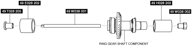
Ring gear shaft component
|
|
22
|
Baffle plate
|
|
23
|
Drive gear case
|
|
24
|
Transfer oil seal (LH)
|
|
25
|
Transfer oil seal (RH) No.3
|
|
26
|
Transfer oil seal (RH) No.2
|
|
27
|
Transfer oil seal (RH) No.1
|
|
28
|
Breather
|
|
29
|
Drain plug, washer
|
|
30
|
Oil level plug, washer
|
Transfer Component Assembly Procedure
1. When disassembling, measure the thickness of the removed spacer and assemble a new spacer with the same dimensions to the drive pinion gear.
bfw4ua00000019
|
Spacer table
|
Identification mark |
Thickness (mm {in}) |
Identification mark |
Thickness (mm {in}) |
|---|---|---|---|
|
08
|
3.080 {0.1213}
|
29
|
3.290 {0.1295}
|
|
09
|
3.095 {0.1219}
|
30
|
3.305 {0.1301}
|
|
11
|
3.110 {0.1224}
|
32
|
3.320 {0.1307}
|
|
12
|
3.125 {0.1230}
|
33
|
3.335 {0.1313}
|
|
14
|
3.140 {0.1236}
|
35
|
3.350 {0.1319}
|
|
15
|
3.155 {0.1242}
|
36
|
3.365 {0.1325}
|
|
17
|
3.170 {0.1248}
|
38
|
3.380 {0.1331}
|
|
18
|
3.185 {0.1254}
|
39
|
3.395 {0.1337}
|
|
20
|
3.200 {0.1260}
|
41
|
3.410 {0.1343}
|
|
21
|
3.215 {0.1266}
|
42
|
3.425 {0.1348}
|
|
23
|
3.230 {0.1272}
|
44
|
3.440 {0.1354}
|
|
24
|
3.245 {0.1278}
|
45
|
3.455 {0.1360}
|
|
26
|
3.260 {0.1283}
|
47
|
3.470 {0.1366}
|
|
27
|
3.275 {0.1289}
|
−
|
−
|
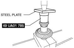
2. Press fit the bearing inner race (front) to the drive pinion gear using the SST and a press.
bfw3ja00000095
|
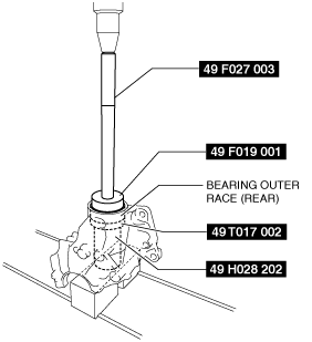
3. Press fit the bearing outer race (rear) to the front carrier using the SST and a press.
bfw4ua00000020
|
4. Press fit the bearing outer race (front) to the front carrier using the SST and a press.
bfw3ja00000097
|
5. Assemble the front carrier to the SST.
bfw4ua00000021
|
6. Assemble a new collapsible spacer to the drive pinion gear component.
7. Assemble the drive pinion gear component to the front carrier.
8. Assemble the bearing inner race (rear) to the drive pinion gear component.
9. Assemble the oil seal using the SST.
bfw3ja00000100
|
10. Apply grease to the area of the companion flange where it contacts the bearing inner race (rear).
11. Assemble the companion flange component to the drive pinion gear component.
12. After applying transfer oil to the thread area of a new locknut, assemble the washer and locknut to the drive pinion gear component.
bfw3ja00000098
|
13. Rotate the companion flange by hand to seat the bearing.
14. Using the SST, gradually tighten the locknut from the minimum specified tightening torque and adjust so that the specified preload is obtained. Record the locknut tightening torque value when the specified preload value is obtained.
bfw3ja00000099
|
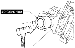
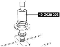
15. Press fit the bearing inner race (LH) to the ring gear shaft using the SST and a press.
bfw4ua00000022
|
16. Press fit the bearing inner race (RH) to the ring gear shaft using the SST and a press.
bfw3ja00000102
|
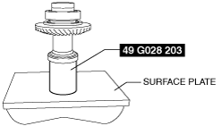
17. Temporarily assemble the bearing outer race (LH) and bearing outer race (RH) to the ring gear shaft.
18. Place the SST on a surface plate as shown in the figure and set the ring gear shaft component on top of it with the bearing outer race (LH) side pointed downward.
bfw4ua00000023
|
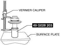
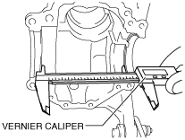
19. Rotate the bearing by hand several times to seat it.
20. Using a vernier caliper, measure the distance between the bearing outer race (LH) and bearing outer race (RH).
bfw4ua00000024
|
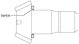
21. Using a vernier caliper, measure the distance shown in the figure for the front carrier.
bfw4ua00000025
|
22. Calculate the total thickness C maximum and minimum values of the adjustment shim using the following formula.
Adjustment shim (LH) table
|
Part number |
Thickness (mm {in}) |
Part number |
Thickness (mm {in}) |
|---|---|---|---|
|
KN01 27 3D1
|
4.490 {0.1768}
|
KN01 27 3F1
|
5.030 {0.1980}
|
|
KN01 27 3D2
|
4.520 {0.1780}
|
KN01 27 3F2
|
5.060 {0.1992}
|
|
KN01 27 3D3
|
4.550 {0.1791}
|
KN01 27 3F3
|
5.090 {0.2004}
|
|
KN01 27 3D4
|
4.580 {0.1803}
|
KN01 27 3F4
|
5.120 {0.2016}
|
|
KN01 27 3D5
|
4.610 {0.1815}
|
KN01 27 3F5
|
5.150 {0.2028}
|
|
KN01 27 3D6
|
4.640 {0.1827}
|
KN01 27 3F6
|
5.180 {0.2039}
|
|
KN01 27 3D7
|
4.670 {0.1839}
|
KN01 27 3F7
|
5.210 {0.2051}
|
|
KN01 27 3D8
|
4.700 {0.1850}
|
KN01 27 3F8
|
5.240 {0.2063}
|
|
KN01 27 3D9
|
4.730 {0.1862}
|
KN01 27 3F9
|
5.270 {0.2075}
|
|
KN01 27 3E1
|
4.760 {0.1874}
|
KN01 27 3G1
|
5.300 {0.2087}
|
|
KN01 27 3E2
|
4.790 {0.1886}
|
KN01 27 3G2
|
5.330 {0.2098}
|
|
KN01 27 3E3
|
4.820 {0.1898}
|
KN01 27 3G3
|
5.360 {0.2110}
|
|
KN01 27 3E4
|
4.850 {0.1909}
|
KN01 27 3G4
|
5.390 {0.2122}
|
|
KN01 27 3E5
|
4.880 {0.1921}
|
KN01 27 3G5
|
5.420 {0.2134}
|
|
KN01 27 3E6
|
4.910 {0.1933}
|
KN01 27 3G6
|
5.450 {0.2146}
|
|
KN01 27 3E7
|
4.940 {0.1945}
|
KN01 27 3G7
|
5.480 {0.2157}
|
|
KN01 27 3E8
|
4.970 {0.1957}
|
KN01 27 3G8
|
5.510 {0.2169}
|
|
KN01 27 3E9
|
5.000 {0.1969}
|
−
|
−
|
Adjustment shim (RH) table
|
Part number |
Thickness (mm {in}) |
Part number |
Thickness (mm {in}) |
|---|---|---|---|
|
KN01 27 355
|
4.490 {0.1768}
|
KN01 27 375
|
5.030 {0.1980}
|
|
KN01 27 356
|
4.520 {0.1780}
|
KN01 27 376
|
5.060 {0.1992}
|
|
KN01 27 357
|
4.550 {0.1791}
|
KN01 27 377
|
5.090 {0.2004}
|
|
KN01 27 358
|
4.580 {0.1803}
|
KN01 27 378
|
5.120 {0.2016}
|
|
KN01 27 359
|
4.610 {0.1815}
|
KN01 27 379
|
5.150 {0.2028}
|
|
KN01 27 361
|
4.640 {0.1827}
|
KN01 27 3B1
|
5.180 {0.2039}
|
|
KN01 27 362
|
4.670 {0.1839}
|
KN01 27 3B2
|
5.210 {0.2051}
|
|
KN01 27 363
|
4.700 {0.1850}
|
KN01 27 3B3
|
5.240 {0.2063}
|
|
KN01 27 364
|
4.730 {0.1862}
|
KN01 27 3B4
|
5.270 {0.2075}
|
|
KN01 27 365
|
4.760 {0.1874}
|
KN01 27 3B5
|
5.300 {0.2087}
|
|
KN01 27 366
|
4.790 {0.1886}
|
KN01 27 3B6
|
5.330 {0.2098}
|
|
KN01 27 367
|
4.820 {0.1898}
|
KN01 27 3B7
|
5.360 {0.2110}
|
|
KN01 27 368
|
4.850 {0.1909}
|
KN01 27 3B8
|
5.390 {0.2122}
|
|
KN01 27 369
|
4.880 {0.1921}
|
KN01 27 3B9
|
5.420 {0.2134}
|
|
KN01 27 371
|
4.910 {0.1933}
|
KN01 27 3C1
|
5.450 {0.2146}
|
|
KN01 27 372
|
4.940 {0.1945}
|
KN01 27 3C2
|
5.480 {0.2157}
|
|
KN01 27 373
|
4.970 {0.1957}
|
KN01 27 3C3
|
5.510 {0.2169}
|
|
KN01 27 374
|
5.000 {0.1969}
|
−
|
−
|
23. Assemble the bearing outer race (LH), bearing outer race (RH), and adjustment shim (LH) and adjustment shim (RH) which were determined by the adjustment shim adjustment to the ring gear shaft.
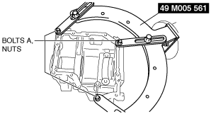
24. Install the SSTs to the ring gear shaft component as shown in the figure.
bfw4ua00000026
|
25. Tighten down the bolts on the left and right of the SST until the ring gear shaft component is assembled to the front carrier.
26. Assemble the ring gear shaft component with the SSTs to the front carrier.
bfw3ja00000106
|
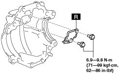
27. Assemble a new baffle plate to the drive gear case.
bfw4ua00000027
|
28. Assemble the drive gear case.
29. Remove the SSTs from the ring gear shaft component.
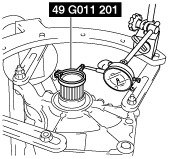
30. Install the SST to the differential engagement area of the ring gear shaft component, and install the dial gauge as shown in the figure.
bfw3ja00000108
|
31. Secure the companion flange (drive pinion gear) and measure the backlash when the ring gear shaft is moved.
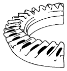
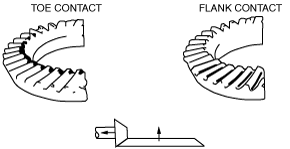
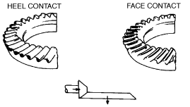
32. Perform the drive pinion gear and ring gear shaft tooth contact inspection.
bawuua00000540
|
bfw4ua00000028
|
bfw2za00000016
|
Spacer table
|
Identification mark |
Thickness (mm {in}) |
Identification mark |
Thickness (mm {in}) |
|---|---|---|---|
|
08
|
3.080 {0.1213}
|
29
|
3.290 {0.1295}
|
|
09
|
3.095 {0.1219}
|
30
|
3.305 {0.1301}
|
|
11
|
3.110 {0.1224}
|
32
|
3.320 {0.1307}
|
|
12
|
3.125 {0.1230}
|
33
|
3.335 {0.1313}
|
|
14
|
3.140 {0.1236}
|
35
|
3.350 {0.1319}
|
|
15
|
3.155 {0.1242}
|
36
|
3.365 {0.1325}
|
|
17
|
3.170 {0.1248}
|
38
|
3.380 {0.1331}
|
|
18
|
3.185 {0.1254}
|
39
|
3.395 {0.1337}
|
|
20
|
3.200 {0.1260}
|
41
|
3.410 {0.1343}
|
|
21
|
3.215 {0.1266}
|
42
|
3.425 {0.1348}
|
|
23
|
3.230 {0.1272}
|
44
|
3.440 {0.1354}
|
|
24
|
3.245 {0.1278}
|
45
|
3.455 {0.1360}
|
|
26
|
3.260 {0.1283}
|
47
|
3.470 {0.1366}
|
|
27
|
3.275 {0.1289}
|
−
|
−
|
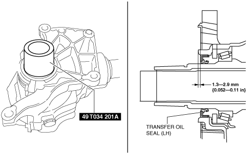
33. Apply a thin layer of sealant (silicone sealant TB1217C or equivalent) to the locations indicated in the figure for the drive gear case.
bfw3ja00000109
|
34. Tighten the drive gear case installation bolts to the specified torque.
35. Using the SST and a hammer, assemble a new transfer oil seal (LH) according to the dimensions shown in the figure.
bfw4ua00000030
|
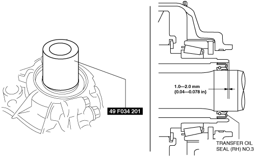
36. Using the SST and a hammer, assemble a new transfer oil seal (RH) No.3 according to the dimensions shown in the figure.
bfw4ua00000031
|
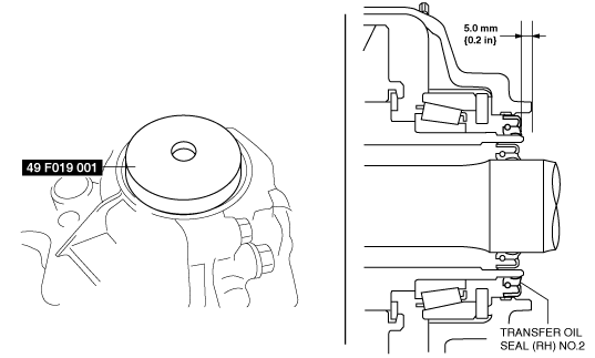
37. Using the SST and a hammer, assemble a new transfer oil seal (RH) No.2 according to the dimensions shown in the figure.
bfw3ja00000114
|
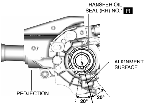
38. Install the new transfer oil seal (RH) No.1 projection to within the range shown in the figure. (with projection type only)
ac9wzw00003856
|
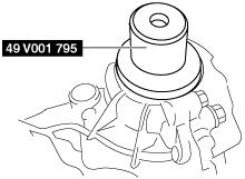
39. Using the SST and a hammer, assemble a new transfer oil seal (RH) No.1
bfw3ja00000115
|
40. Assemble a new breather.
41. Assemble a new washer and drain plug.
42. Assemble a new washer and oil level plug.