 |
am6zzn00005538
AIM OF DEVELOPMENT
id000000100100
Product Concept
Vehicle Outline
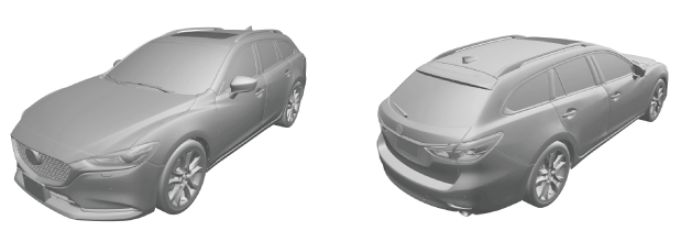
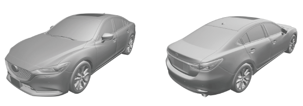
Exterior design
External view
4SD
am6zzn00005538
|
WGN
am6zzn00005539
|
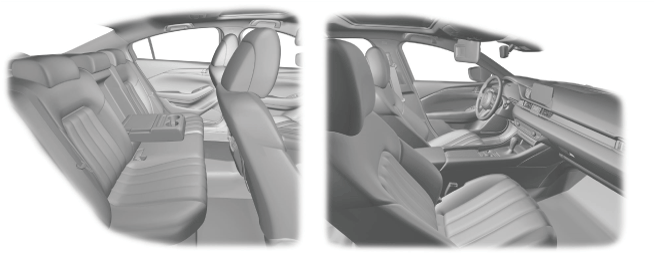
Interior design
am6zzn00005540
|
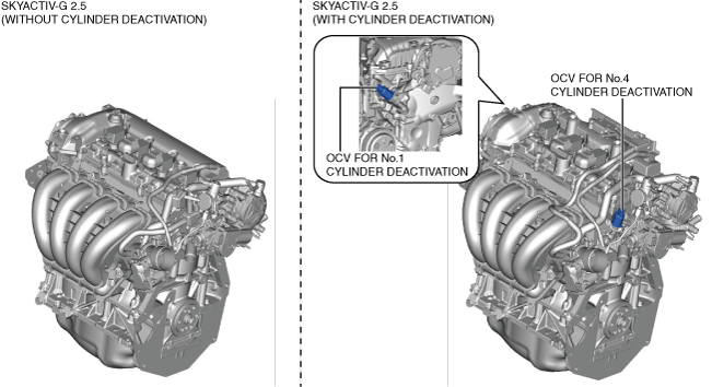
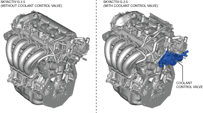
Engine
ac5uun00003731
|
am6xun00003847
|
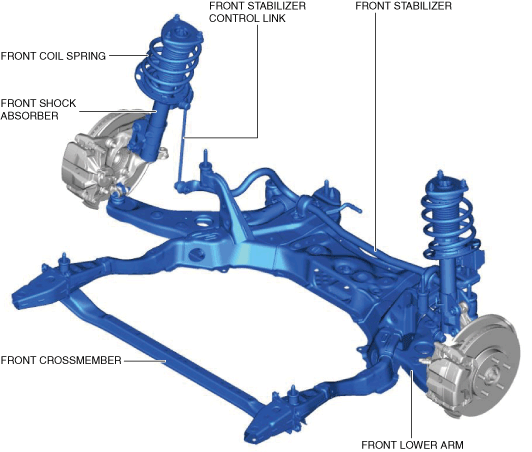
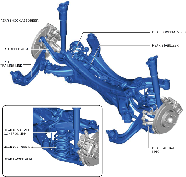
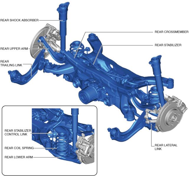
Suspension
am6xun00004370
|
2WD
am6xun00004371
|
4WD
am6xun00004372
|
Driveline/axle
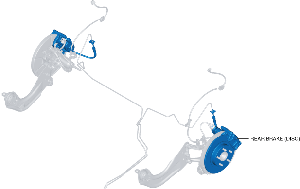
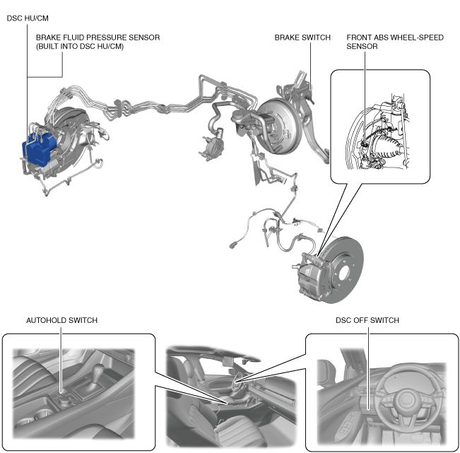
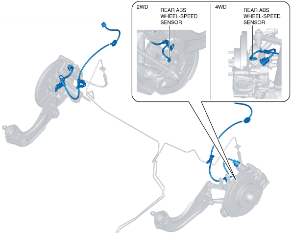
Brakes
Vehicle front side
am6zzn00005655
|
Vehicle rear side
am6zzn00003861
|
Vehicle front side
am6xun00004892
|
Vehicle rear side
am6zzn00004992
|
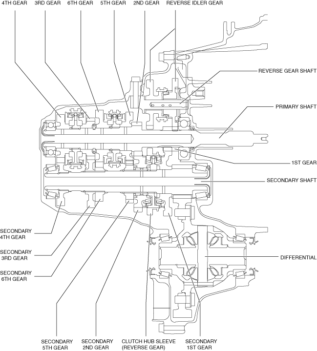
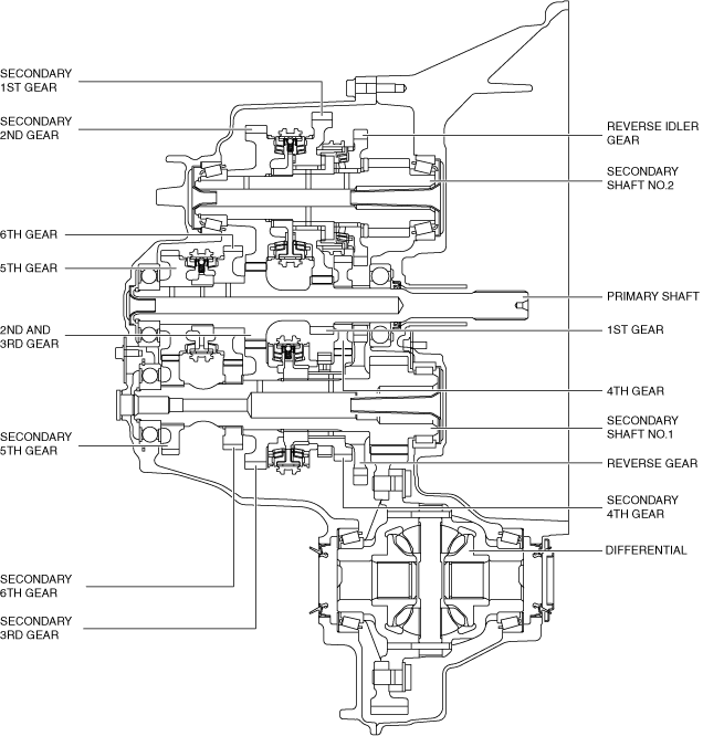
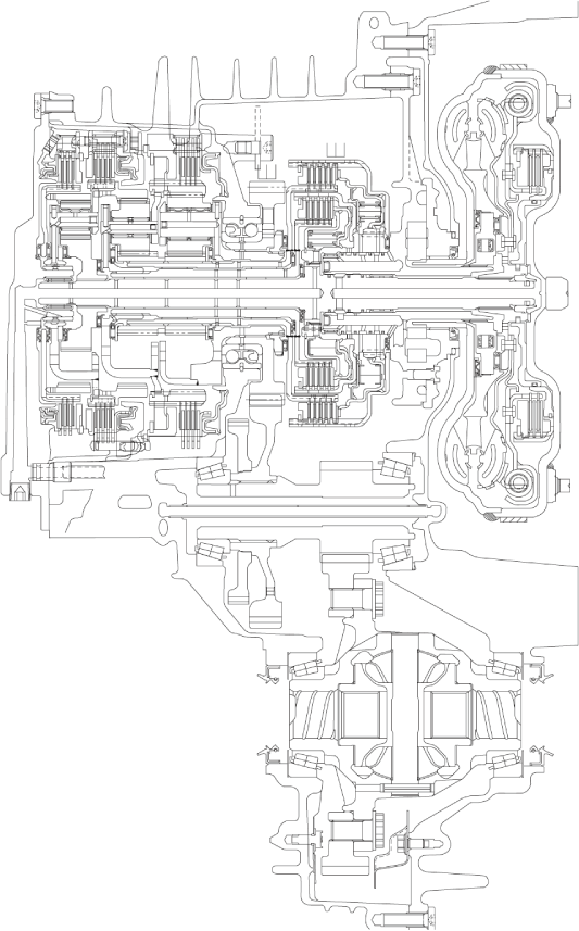
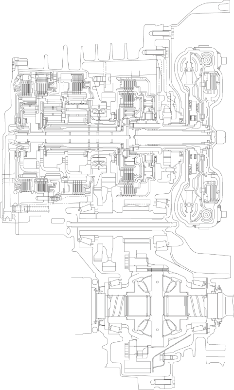
Transaxle
am3uun00001754
|
am6zzn00002618
|
am3uun00002419
|
ac5jjn00001299
|
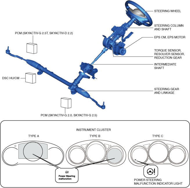
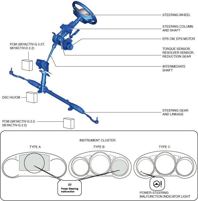
Steering
L.H.D.
am6zzn00005571
|
R.H.D.
am6zzn00005966
|
Heater, ventilation and air conditioning
Restraints
|
Seat position |
Air bag module |
Seat belt |
|||||
|---|---|---|---|---|---|---|---|
|
Driver-side air bag module |
Passenger-side air bag module |
Side air bag module |
Curtain air bag module |
ELR (Emergency Locking Retractor) |
Load limiter |
Front pre-tensioner seat belt |
|
|
Driver's seat
|
×
|
—
|
×
|
×
|
×
|
×
|
×
|
|
Passenger's seat
|
—
|
×
|
×
|
×
|
×
|
×
|
×
|
|
Rear seat (LH/RH)
|
—
|
—
|
—
|
×
|
×
|
—
|
—
|
|
Rear seat (center)
|
—
|
—
|
—
|
—
|
×
|
—
|
—
|
|
Seat position |
Air bag module |
Seat belt |
|||||||
|---|---|---|---|---|---|---|---|---|---|
|
Driver-side air bag module |
Passenger-side air bag module |
Side air bag module |
Curtain air bag module |
ELR (Emergency Locking Retractor) |
Load limiter |
ALR (Automatic Locking Retractor) |
Front pre-tensioner seat belt |
Rear pre-tensioner seat belt |
|
|
Driver's seat
|
×
|
—
|
×
|
×
|
×
|
×
|
—
|
×
|
—
|
|
Passenger's seat
|
—
|
×
|
×
|
×
|
×
|
×
|
—
|
×
|
—
|
|
Rear seat (LH/RH)
|
—
|
—
|
—
|
×
|
×
|
×
|
×*
|
—
|
×
|
|
Rear seat (center)
|
—
|
—
|
—
|
—
|
×
|
—
|
—
|
—
|
—
|
i-ACTIVSENSE
|
System |
Outline |
Reference |
|---|---|---|
|
Mazda Radar Cruise Control (MRCC) system
|
The Mazda radar cruise control (MRCC) system can perform headway control and maintain a constant speed at a set vehicle speed and distance from a vehicle ahead using a radar unit which detects the vehicle ahead without the driver having to depress the accelerator or brake pedal. Additionally, if the detecting vehicle approaches the vehicle ahead too closely such as when the vehicle ahead is braking suddenly, the system alerts the driver using a warning sound and warning indication.
|
|
|
Mazda radar cruise control with stop & go function (MRCC with stop & go function)
|
The Mazda Radar Cruise Control with Stop & Go function (MRCC with Stop & Go function) uses a radar unit to detect a vehicle ahead, and performs headway control to maintain a constant distance from a vehicle ahead without the driver having to depress the accelerator or brake pedal. Additionally, if the vehicle ahead stops during headway control, the vehicle automatically stops and maintains a stopped condition. If the vehicle approaches the vehicle ahead too closely such as when the vehicle ahead is braking suddenly, the system alerts the driver using a warning sound and warning indication.
|
|
|
Distance Recognition Support System (DRSS)
|
For the distance recognition support system (DRSS), the radar unit calculates the distance between the vehicle and a vehicle ahead, and displays the distance between the vehicle and a vehicle ahead in the multi-information display.
|
|
|
Lane-keep assist system
|
The lane-keep assist system detects the white lines (yellow lines) of the vehicle lane using the Forward Sensing Camera (FSC) installed to the windshield, and alerts the driver that the vehicle may be deviating from its lane and it provides steering assistance to help the driver stay within the vehicle lanes.
|
(See LANE-KEEP ASSIST SYSTEM.)
|
|
Lane Departure Warning System (LDWS)
|
The Lane Departure Warning System (LDWS) recognizes vehicle lane lines on a road using the forward sensing camera (FSC) installed to the windshield, and if the vehicle departs from its lane unbeknownst to the driver, the system alerts the driver of the lane departure using a warning indication and warning sound.
|
|
|
Adaptive LED headlights
|
The adaptive LED headlights improve visibility by changing the headlight illumination range depending on the vehicle driving conditions and the surrounding conditions without switching the headlights between HI/LO.
|
(See ADAPTIVE LED HEADLIGHTS.)
|
|
High Beam Control (HBC) System
|
The High Beam Control (HBC) system turns the headlights HI off when the forward sensing camera (FSC) installed to the windshield recognizes a vehicle ahead and when traveling through towns and cities while the vehicle is being driven with the headlights HI turned on. Due to this, blinding of other vehicles from headlight glare is prevented and driver visibility is assured.
|
|
|
Adaptive Front lighting System (AFS)
|
The adaptive front lighting system (AFS) is a system which enhances the range of visibility when the headlights are turned on by pointing the optical axis of the headlights in the direction in which the steering wheel is operated according to the steering operation.
|
|
|
Blind Spot Monitoring (BSM) system
|
The blind spot monitoring (BSM) system detects a vehicle in the blind-spot area at the rear of the vehicle to alert the driver of the possible collision with a target vehicle using the BSM indicator light on the outer mirror glass, the rear crossing traffic alert (RCTA) indicator light displayed on the rear view monitor screen, and the blind spot monitoring (BSM) warning alarm.
|
|
|
Driver attention alert system
|
The driver attention alert system warns the driver using the warning display and sound if it detects the driver's lack of attentiveness.
|
|
|
Traffic sign recognition system (TSR)
|
The traffic sign recognition system (TSR) provides support for safe driving by displaying traffic signs on the active driving display or by notifying the driver of excessive speed.
|
|
|
360°VIEW MONITOR SYSTEM
|
The 360° view monitor system is a safety system supporting the driver in all directions to prevent accidents by reducing the driver's blind spots.
|
(See 360°VIEW MONITOR SYSTEM.)
|
|
Adjustable speed limiter
|
• For the purpose of safety performance improvement, the adjustable speed limiter restricts unintended excess vehicle speed by allowing the driver to optionally set the maximum vehicle speed.
• The adjustable speed limiter restricts the engine output so that the vehicle speed does not exceed the set maximum vehicle speed even if the accelerator pedal is being depressed.
• The adjustable speed limiter does not operate simultaneously with the cruise control system.
|
(See ADJUSTABLE SPEED LIMITER.)
|
|
System |
Outline |
Reference |
|---|---|---|
|
Smart Brake Support (SBS)
|
• With the Smart Brake Support (SBS) system, the radar unit, laser sensor and Forward Sensing Camera (FSC) detect the distance to a vehicle ahead or an obstruction while the vehicle is traveling at a speed of 15 km/h {9.4 mph} or more, and if the radar unit determines that there is a danger of a collision, the driver is alerted by a warning message and a warning sound activated intermittently.
• If the possibility of a collision increases, the system operates the brakes automatically to decrease the damage from the collision.
|
(See SMART BRAKE SUPPORT (SBS).)
|
|
Advanced Smart City Brake Support (Advanced SCBS)
|
With the Advanced Smart City Brake Support (Advanced SCBS) system, if a possible collision with a vehicle ahead or pedestrian is detected while the vehicle is traveling at a low speed, the system applies the brakes automatically to reduce the damage from the collision.
|
|
|
Smart City Brake Support [Forward] (SCBS F)
|
With the Smart City Brake Support [Forward] (SCBS F) system, if a possible collision with a vehicle ahead or an obstruction is detected while the vehicle is traveling at a low speed, the system applies the brakes automatically to reduce the damage from the collision.
|
|
|
Smart City Brake Support [Reverse] (SCBS R)
|
With the Smart City Brake Support [Reverse] (SCBS R) system, if a possible collision with vehicles/obstructions while reversing increases due to the driver not confirming the safety, the system applies the brakes automatically to reduce the damage from the collision.
|