 |
am6zzw00014381
DTC P0402:00 [PCM (SKYACTIV-D 2.2)]
id0102j5155200
Details on DTCs
|
System malfunction location |
EGR control system: Excess EGR inducted |
|
|---|---|---|
|
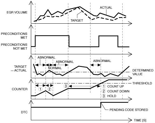
Detection condition
|
Determination condition
|
• The EGR volume is more than 0.3 g/rev of the target value for a continuous 8.2 s.
|
|
Preconditions
|
• During EGR control
• Engine speed:1,300 to 6,000 rpm
• Fuel injection amount: 15 to 50 mm3/st
• Engine torque: 80 to 240 Nm
• The following DTCs are not detected
|
|
|
Drive cycle
|
• 1
|
|
|
Self-test type
|
• CMDTC self test
|
|
|
Sensor/unit used
|
• EGR valve
• EGR cooler bypass valve
• Intake shutter valve
• MAF sensor
• MAP sensor No.2
• Boost air temperature sensor
• Exhaust gas pressure sensor No.1
• Exhaust gas temperature sensor No.1
|
|
|
Fail-safe
|
• Limits engine torque./ Limits the maximum engine speed.
• Inhibits the automatic diesel particulate filter regeneration control.
• Inhibits the manual diesel particulate filter regeneration control.
• Inhibits the EGR control.
• Inhibits engine-stop by i-stop control.
|
|
|
Vehicle status when DTCs are output
|
• Check engine light turns on
|
|
|
Possible cause
|
• PCM input signal error
• Intake shutter valve malfunction
• EGR valve malfunction (stuck open)
• EGR cooler bypass valve malfunction (stuck open)
• Air suction from intake-air system piping (between turbocharger and intake manifold)
• Restriction in EGR system piping
• PCM malfunction
|
|
System Wiring Diagram
Function Explanation (DTC Detection Outline)
am6zzw00014381
|
Repeatability Verification Procedure
PID Item/Simulation Item Used in Diagnosis
PID
|
Item name |
Outline |
Unit |
Display/condition |
|---|---|---|---|
|
EXHPRES1
|
Exhaust gas pressure (No.1)
|
kPa
|
• Idle: Approx. 100 kPa
• Racing (engine speed 4,000 rpm): Approx. 193 kPa
• Racing (engine speed 5,000 rpm): Approx. 266 kPa
|
|
EXHTEMP1
|
Exhaust gas temperature (No.1)
|
°C
|
• Displays exhaust gas temperature (No.1)
|
|
CACT12
|
Boost air temperature
|
°C
|
• Displays boost air temperature
|
|
MAF
|
Intake air amount
|
g/sec
|
• Ignition switched ON: Approx. 1.0 g/sec
• Idle: Approx. 5.4 g/sec
• Racing (engine speed 2,000 rpm): Approx. 13.84 g/sec
• Racing (engine speed 4,000 rpm): Approx. 85.13 g/sec
|
|
MAP
|
Intake air pressure (No.2)
|
kPa
|
• Displays intake air temperature (No.2)
|
Function Inspection Using M-MDS
|
Step |
Inspection |
Results |
Action |
|---|---|---|---|
|
1
|
PURPOSE: VERIFY DTC CAUSING FREEZE FRAME DATA
• Is DTC P0402:00 causing the freeze frame data?
|
Yes
|
Go to the next step.
|
|
No
|
Inspect the DTC causing the freeze frame data.
|
||
|
2
|
PURPOSE: RECORD VEHICLE STATUS AT TIME OF DTC DETECTION TO UTILIZE WITH REPEATABILITY VERIFICATION
• Record the freeze frame data/snap shot data.
|
―
|
Go to the next step.
|
|
3
|
PURPOSE: VERIFY OTHER RELATED DTCs
• Switch the ignition OFF, and then switch it ON (engine off).
• Display the DTCs using the M-MDS.
• Has any DTC other than P0402:00 been stored?
|
Yes
|
Repair the malfunctioning location according to the applicable DTC troubleshooting.
|
|
No
|
Go to the next step.
|
||
|
4
|
PURPOSE: VERIFY RELATED SENSOR INPUT SIGNAL
• Start the engine and warm it up.
• Display the following PIDs using the M-MDS.
• Are the monitoring values normal?
|
Yes
|
Go to Troubleshooting Diagnostic Procedure to perform the procedure from step 1.
|
|
No
|
Go to the next step.
|
||
|
5
|
PURPOSE: INSPECT WIRING HARNESSES AND CONNECTORS FOR RELATED-SENSOR
• Display the following PIDs using the M-MDS.
• When the PCM, MAF sensor, MAP sensor No.2, boost air temperature sensor, exhaust gas pressure sensor No.1, and exhaust gas temperature sensor No.1 connectors are shaken, does the PID value include a PID item which has changed?
|
Yes
|
Inspect the related wiring harnesses and connectors.
• Repair or replace the malfunctioning location.
Go to Troubleshooting Diagnostic Procedure to perform the procedure from step 6.
|
|
No
|
Go to Troubleshooting Diagnostic Procedure to perform the procedure from step 1.
|
Troubleshooting Diagnostic Procedure
|
Step |
Inspection |
Results |
Action |
|---|---|---|---|
|
1
|
PURPOSE: INSPECT INTAKE SHUTTER VALVE
• Inspect the intake shutter valve.
• Is the intake shutter valve normal?
|
Yes
|
Go to the next step.
|
|
No
|
Replace the intake shutter valve, then go to Step 6.
|
||
|
2
|
PURPOSE: VERIFY EGR CONTROL VALVE OPERATION CONDITION
• Perform the EGR control inspection.
• Is the EGR valve operation normal?
|
Yes
|
Go to the next step.
|
|
No
|
Repair or replace the malfunctioning location, then go to Step 6.
|
||
|
3
|
PURPOSE: VERIFY EGR COOLER BYPASS VALVE OPERATION CONDITION
• Perform the EGR control inspection.
• Is the EGR cooler bypass valve operation normal?
|
Yes
|
Go to the next step.
|
|
No
|
Repair or replace the malfunctioning location, then go to Step 6.
|
||
|
4
|
PURPOSE: INSPECT INTAKE AIR SYSTEM FOR AIR SUCTION
• Visually inspect the following intake air system for looseness or damage.
• Is the intake air system normal?
|
Yes
|
Go to the next step.
|
|
No
|
Repair or replace the malfunctioning location, then go to Step 6.
|
||
|
5
|
PURPOSE: INSPECT EGR PASSAGE FOR CLOGGING
• Switch the ignition OFF.
• Remove the EGR valve.
• Is the gasket correctly installed? Visually inspect the EGR passage for clogging.
• Is the EGR passage normal?
|
Yes
|
Go to the next step.
|
|
No
|
Repair or replace the malfunctioning location, then go to the next step.
|
||
|
6
|
PURPOSE: VERIFICATION OF VEHICLE REPAIR COMPLETION
• Reconnect all disconnected connectors and hoses.
• Refer to the [MEMORY CLEARING PROCEDURE] and clear the DTC.
• Implement the repeatability verification procedure.
• Display the DTCs using the M-MDS.
• Is DTC P0402:00 displayed?
|
Yes
|
Repeat the inspection from Step 1.
• If the malfunction recurs, replace the PCM, then go to the next step.
|
|
No
|
Go to the next step.
|
||
|
7
|
PURPOSE: VERIFY IF THERE IS ANY OTHER MALFUNCTION
• Has any other DTC or pending code been stored?
|
Yes
|
Repair the malfunctioning location according to the applicable DTC troubleshooting.
|
|
No
|
DTC troubleshooting completed.
|