HYDRAULIC LASH ADJUSTER (HLA) REMOVAL/INSTALLATION [SKYACTIV-G 2.5T]
id0110q8804100
-
Warning
-
• A hot engine can cause severe burns. Turn off the engine and wait until it is cool before servicing.
-
Caution
-
• If the camshaft is rotated with the timing chain removed and the piston at the top dead center position, the valve may contact the piston and the engine could be damaged. When rotating the camshaft with the timing chain removed, rotate it after lowering the piston from the top dead center position.
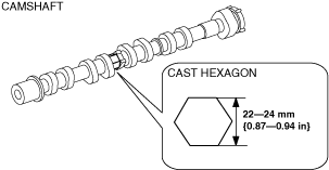
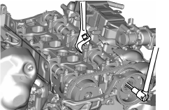
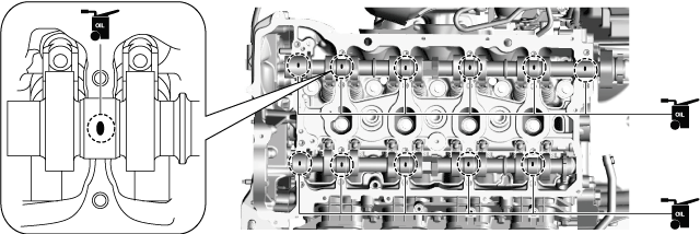
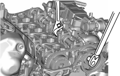
• When rotating the camshaft using a wrench on the cast hexagon, the wrench may contact the rocker arm and damage the rocker arm. To prevent damage to the rocker arm when holding the camshaft on the cast hexagon, use a wrench on the rear side of the engine as shown in the figure to secure a clearance between the cam.
• Carefully assemble the HLA because the specification is different between the intake side and the exhaust side.
-
Note
-
• Width at the cast hexagon of the camshaft is 22—24 mm {0.87—0.94 in}.
1. Disconnect the negative battery terminal. (See NEGATIVE BATTERY TERMINAL DISCONNECTION/CONNECTION.)
2. Remove the plug hole plate. (See PLUG HOLE PLATE REMOVAL/INSTALLATION [SKYACTIV-G 2.5T].)
3. Remove the ignition coil/ion sensors. (See IGNITION COIL/ION SENSOR REMOVAL/INSTALLATION [SKYACTIV-G 2.5T].)
4. Remove the cylinder head cover. (See TIMING CHAIN REMOVAL/INSTALLATION [SKYACTIV-G 2.5T].)
5. Remove the front under cover No.2. (See FRONT UNDER COVER No.2 REMOVAL/INSTALLATION.)
6. Remove the front splash shield (RH). (See SPLASH SHIELD REMOVAL/INSTALLATION.)
7. Remove the electric variable valve timing motor/driver. (See ELECTRIC VARIABLE VALVE TIMING MOTOR/DRIVER REMOVAL/INSTALLATION [SKYACTIV-G 2.5T].)
8. Remove the vacuum pump. (See VACUUM PUMP REMOVAL/INSTALLATION [SKYACTIV-G 2.5T].)
9. Remove the high pressure fuel pump and rear housing. (See HIGH PRESSURE FUEL PUMP REMOVAL/INSTALLATION [SKYACTIV-G 2.5T].)
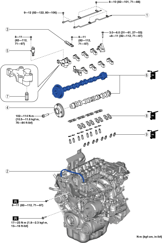
10. Remove in the order indicated in the table.
11. Install in the reverse order of removal.
12. Start the engine and inspect the following:
-
|
1
|
Oil shower pipe
|
|
2
|
Timing chain
|
|
3
|
Chain guide (No.1)
|
|
4
|
Electric variable valve timing actuator
|
|
5
|
OCV
|
|
6
|
Camshaft
|
|
7
|
OCV oil filter
|
|
8
|
Rocker arm
|
|
9
|
HLA
|
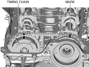
Timing Chain Removal Note
1. Release the tension on the timing chain using the following procedure:
-
Note
-
• Release the tension on the timing chain by securing the timing chain tensioner arm through the service hole on the engine front cover.
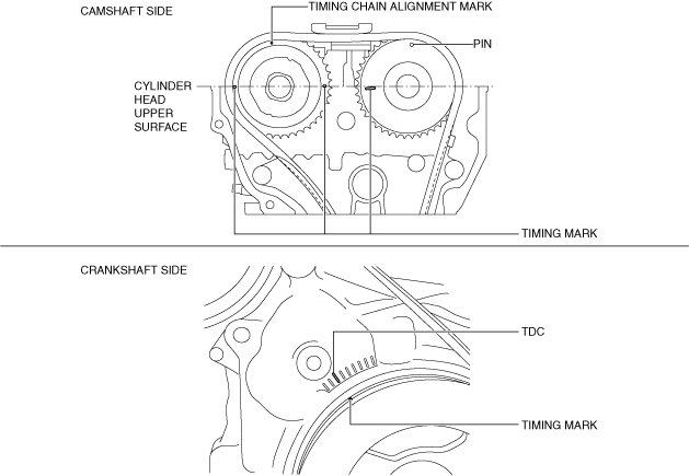
- (1) Rotate the crankshaft clockwise so that cylinder No.1 is positioned around before top dead center (TDC) as shown in the figure.
-
-
Note
-
• With cylinder No.1 positioned around before top dead center (TDC), there is no large movement (rotation) of the exhaust camshaft when the timing chain is removed. Therefore, installation of the electric variable valve timing actuator to the camshaft will be easier. (If there is a large movement of the exhaust camshaft, installation of the electric variable valve timing actuator to the camshaft must be performed while loosening the chain by rotating the exhaust camshaft.)
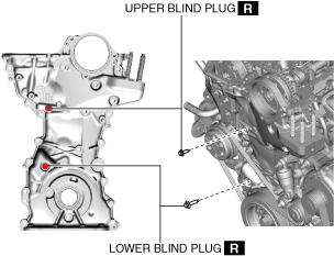
- (2) Remove the blind plugs (upper and lower) on the engine front cover service holes.
-
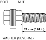
- (3) Assemble several washers and a nut to an M6 bolt (35—60 mm {1.4—2.3 in}), entirely threaded type as shown in the figure.
-
-
Caution
-
• If the thread area exceeds the length shown in the figure, the tensioner arm could be damaged when fixing it. Adjust the number of washers so that the thread area does not exceed the length shown in the figure.
-
Note
-
• The bolt contacts the tensioner arm when it is inserted approx. 20 mm {0.79 in}.
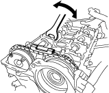
• Hold the exhaust camshaft using a wrench on the cast hexagon and move it back and forth a few times as shown in the figure. This will drain the oil from the chain tensioner and make the following servicing easier.
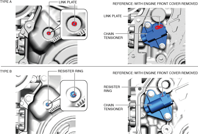
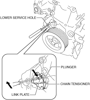
- (4) Verify the chain tensioner shape from the lower service hole and identify the chain tensioner type.
-
-
Note
-
• Verifying the chain tensioner type is necessary because the following procedures may differ according to the type of tensioner.
- (5) Insert a precision screwdriver into the lower service hole. (Chain tensioner type A)
-
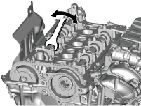
- (6) While moving the exhaust camshaft back and forth in the direction of the arrow using a wrench on the cast hexagon, press down the link plate of the timing chain tensioner using a precision screwdriver and release the plunger lock. (Chain tensioner type A)
-
-
Note
-
• When moving the exhaust camshaft back and forth, the timing chain pushes the plunger in the chain tensioner making it easier to operate the link plate.
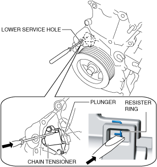
- (7) Insert a thin flathead screwdriver (precision screwdriver) into the lower service hole and press the chain tensioner resister ring. (Chain tensioner type B)
-
-
Caution
-
• If excessive force is applied to the resister ring, it may cause the resister ring to deform. When pressing the resister ring, be careful not to apply excessive force.
-
Note
-
• The plunger lock is released by pressing the chain tensioner resister ring.
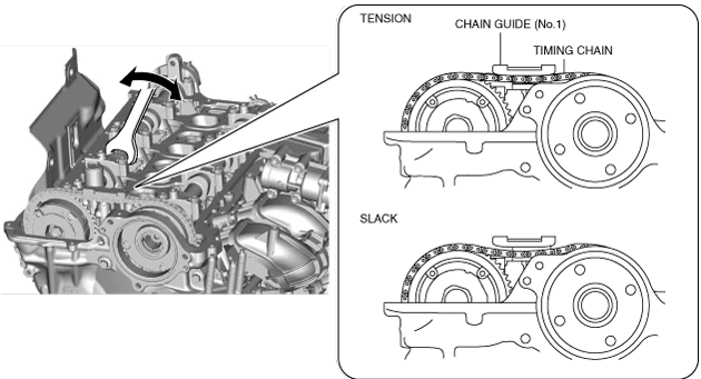
- (8) With the plunger lock released, rotate the exhaust camshaft clockwise until the timing chain loosens.
-
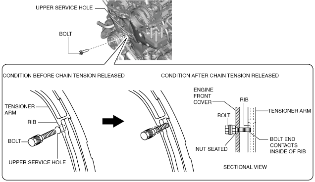
- (9) With the chain loosened, screw the bolt prepared in Step 3 into the upper service hole by hand until the nut is seated and the tensioner arm is fixed.
-
-
Caution
-
• If the bolt cannot be screwed-in until the nut is seated or if resistance can be felt when screwing-in the bolt, the tensioner arm could be damaged by the bolt. Because it is possible that the plunger lock of the chain tensioner cannot be released or there is a lack of chain looseness, remove the bolt and repeat the procedure from Step 5.
-
Note
-
• When the exhaust camshaft is rotated clockwise, the tensioner arm is pressed by the dynamic chain and moved outside of the engine. When the bolt is screwed in under this condition, the bolt end contacts the inside of the tensioner rib, fixing the tensioner arm and releasing the tension on the chain.
- (10) After securing the tensioner arm, remove the chain guide (No.1).
-
Electric Variable Valve Timing Actuator Removal Note
-
Caution
-
• Keep the timing chain pulled up during and after the work in which it has been set aside from the sprocket. If the chain falls down, it may disengage from the sprocket on the crankshaft side and deviate, leading to valve timing deviation.
• After servicing, always verify the valve timing.
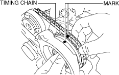
1. Mark the timing chain and each actuator so that they can be reassembled in the same condition as before removal.
2. Hold the intake camshaft using a wrench on the cast hexagon and remove the electric variable valve timing actuator installation bolt.
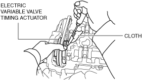
3. Using a screwdriver wrapped in a clean cloth, lightly press the electric variable valve timing actuator to the front and separate the intake camshaft and the actuator.
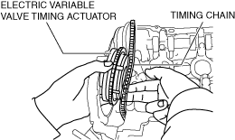
4. Remove the timing chain from the exhaust and intake camshaft sprockets and set is aside, and remove the electric variable valve timing actuator.
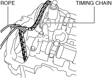
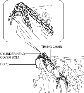
5. Return the timing chain to the exhaust camshaft sprocket, and pull the timing chain up and suspend it using a rope as shown in the figure.
Camshaft Removal Note
-
Caution
-
• Keep the timing chain pulled up during and after the work in which it has been set aside from the sprocket. If the chain falls down, it may disengage from the sprocket on the crankshaft side and deviate, leading to valve timing deviation.
• After servicing, always verify the valve timing.
-
Note
-
• Remove the exhaust camshaft and the hydraulic variable valve timing actuator as a single unit.
1. Leave the timing chain as it is, which was suspended after electric variable valve timing actuator removal.
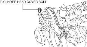
2. Temporarily install the cylinder head cover bolt to the position shown in the figure to use it for suspending the timing chain.
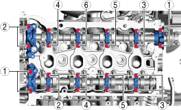
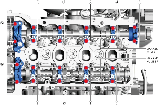
3. Loosen the camshaft cap bolts in two or three passes in the order shown in the figure, and remove the camshaft caps.
4. Remove the intake camshaft.
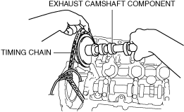
5. While setting the timing chain aside, remove the hydraulic variable valve timing actuator and the exhaust camshaft as a single unit.
6. Pull up the timing chain and suspend it using a rope as shown in the figure.
Rocker Arm Removal Note
1. Remove the rocker arms, clips and HLAs as a single unit. (only when removing rocker arms on exhaust side)
-
Note
-
• If the rocker arm is not replaced, it is not necessary to perform Step 2.
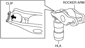
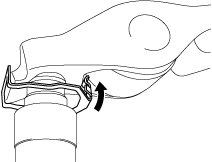
2. Press the clip in the direction of the arrow to remove it, and then remove the rocker arm. (only when removing rocker arms on exhaust side)
-
Note
-
• The HLA is also removed under this condition.
3. Keep the rocker arms in the order of removal to enable reassembly in their original positions.
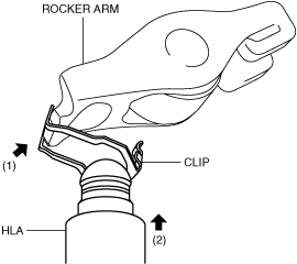
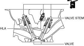
HLA Removal Note
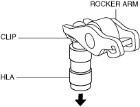
1. Remove the HLA with the rocker arm, clip, and HLA as a single unit by pulling it in the direction of the arrow shown in the figure. (only when removing HLA on exhaust side)
2. Keep the HLAs in the order of removal to enable reassembly in their original positions.
HLA Installation Note
1. Perform HLA air bleeding using the following procedure.
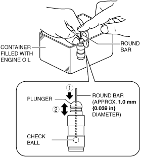
- (1) Put the HLA in a container filled with engine oil.
-
-
Caution
-
• Do not insert the round bar firmly because the check ball spring force is extremely weak.
- (2) While lightly pressing the check ball using a round bar (approx. 1.0 mm {0.039 in} diameter), bleed air by moving the plunger up and down.
-
- (3) Press the end of the plunger in the oil and verify that there is no rebounding feel.
-
-
• If rebounding feel cannot be eliminated, replace the HLA.
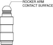
2. Visually inspect the HLA surface where it contacts the rocker arm.
-
• If there is any malfunction, replace the HLA.
3. Assemble the HLAs to their original positions. (intake side)
4. Apply engine oil to the HLAs surface where it contacts the rocker arms. (exhaust side)
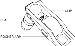
5. Assemble the HLAs using the following procedure: (exhaust side)
- (1) Press the clip onto the rocker arm.
-
- (2) Insert the HLA from the underside of the clip.
-
- (3) Press the clip in the direction of the arrow and install it to the rocker arm.
-
- (4) Verify that the tab of the clip is securely engaged to the rocker arm.
-
Rocker Arm Installation Note
1. Apply engine oil to the HLAs and the end of the valve stems.
2. Install the rocker arms to the same positions as before removal. (intake side)
3. Install the rocker arms, clips and HLAs as a single unit to the same positions as before removal. (exhaust side)
Camshaft Installation Note
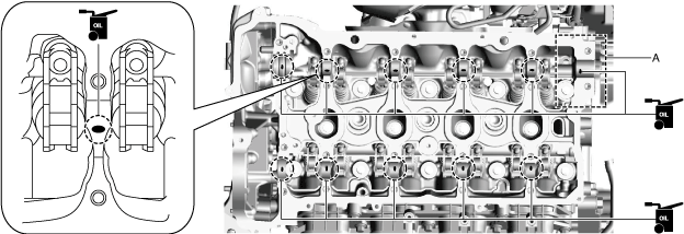
1. Apply SAE 90 gear oil or equivalent, or engine oil to the positions shown in the figure.
-
Caution
-
• Apply 0.05 ml {0.05 cc, 0.003 in3} or less of oil to area A in the figure.
2. Apply gear oil (SAE 90 or equivalent) or engine oil to the thrust surface (both surfaces front and back) of the front journal on each camshaft.
-
Note
-
• If oil is applied to the front camshaft cap, oil should not be applied to the thrust surface of the front journal.
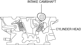
3. As shown in the figure, align the cam position of cylinder No.1 around top dead center (TDC) and place the intake camshaft on the cylinder head.
4. Remove the rope suspending the timing chain on the exhaust side.
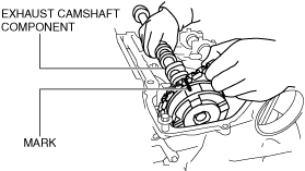
5. While aligning the mark on the timing chain placed during removal with the one on the hydraulic variable valve timing actuator, place the exhaust camshaft component on the cylinder head.
6. Apply SAE 90 gear oil or equivalent, or engine oil to the central area of each journal on the camshaft.
7. Apply SAE 90 gear oil or equivalent, or engine oil to the thrust surface of the front camshaft cap.
-
Note
-
• If oil is applied to the front journal thrust surface of each camshaft, oil should not be applied to the front camshaft cap.
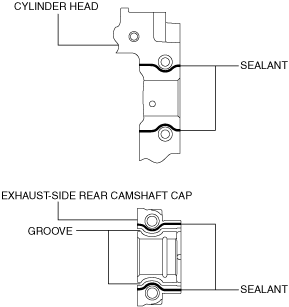
8. Apply sealant (LOCTITE 962T, 518, 272 or equivalent) to the rear camshaft cap installation area on the exhaust side of the cylinder head or the rear camshaft cap on the exhaust side.
-
Note
-
• To prevent engine oil leakage, apply sealant to the rear camshaft cap installation area on the exhaust side or the rear camshaft caps on the exhaust side of the cylinder head, and seal the journal.
-
Caution
-
• Do not spill sealant on the journal.
-
Sealant agent bead width
-
1—3 mm {0.04—0.11 in}
9. Install the camshaft caps in the marked number order, and temporarily tighten the camshaft cap installation bolts in two or three passes evenly.
10. Tighten the camshaft cap installation bolts in two steps in the order shown in the figure.
-
Tightening torque
-
Step 1: 3.0—6.0 N·m {31—61 kgf·cm, 27—53 in·lbf}
Step 2: 8—11 N·m {82—112 kgf·cm, 71—97 in·lbf}
Electric Variable Valve Timing Actuator Installation Note
1. Remove the rope suspending the timing chain on the intake side.
2. Remove the timing chain from the exhaust and intake camshaft sprockets and set it aside to the rear, then insert the electric variable valve timing actuator between the engine front cover and the cylinder head.
3. Return the timing chain to the exhaust camshaft sprocket.
4. While aligning the mark on the timing chain placed during removal with the one on the electric variable valve timing actuator, engage the chain with the sprocket.
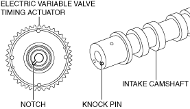
5. Align the knock pin on the end of the intake camshaft with the notch on the actuator side, then assemble the actuator.
-
Note
-
• Adjust the knock pin with the notch while adjusting the knock pin position by rotating the camshaft.
6. Hold the intake camshaft using a wrench on the cast hexagon, and tighten the electric variable valve timing actuator installation bolt.
-
Tightening torque
-
102—114 N·m {10.5—11.6 kgf·m, 76—84 ft·lbf}
Timing Chain Installation Note
1. Install the chain guide (No.1).
-
Tightening torque
-
8—11 N·m {82—112 kgf·cm, 71—97 in·lbf}
2. Remove the bolt securing the tensioner arm and apply tension to the timing chain.
3. Inspect the timing chain for looseness.
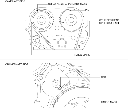
4. Verify that the alignment marks on each sprocket and the timing chain are aligned.
-
Note
-
• The timing mark of SKYACTIV-G 2.5T is not completely parallel with the upper surface of the cylinder head.
5. Install the blind plugs (upper and lower) for the engine front cover service holes.
-
Tightening torque
-
Upper: 8—11 N·m {82—112 kgf·cm, 71—97 in·lbf}
Lower: 17—23 N·m {1.8—2.3 kgf·m, 13—16 ft·lbf}
Oil Shower Pipe Installation Note
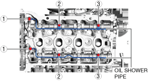
1. Install the oil shower pipe in the order shown in the figure.
Tightening torque
|
Installation position
|
Tightening torque
|
|
1
|
9—12 N·m {92—122 kgf·cm, 80—106 in·lbf}
|
|
2, 3
|
8.0—10.0 N·m {82—101 kgf·cm, 71—88 in·lbf}
|