 |
ac5wzw00010778
ENGINE DISASSEMBLY/ASSEMBLY [SKYACTIV-G 2.5 (WITH CYLINDER DEACTIVATION)]
id0110s8800500
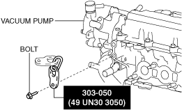
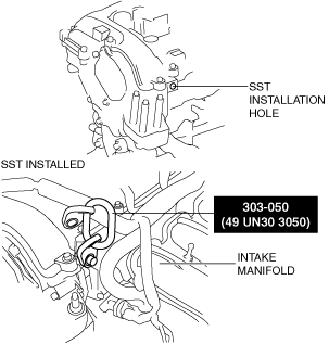
1. Install the SST using part number 99794 1025 or an M10 x 1.25, length 25 mm {0.98 in} bolt as shown in the figure.
Engine front side
ac5wzw00010778
|
Engine rear side
ac5uuw00006888
|
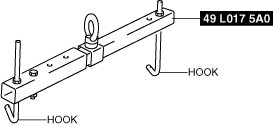
2. Engage the hooks of the SST (49 L017 5A0) to the SST (49 UN30 3050).
ac5uuw00006889
|
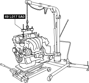
3. To ensure the safety of the work (control engine and transaxle sway), set a hoist as shown in the figure.
ac5uuw00006890
|
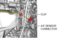
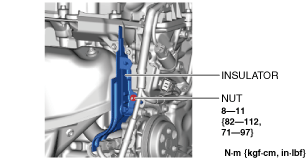
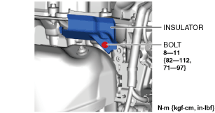
4. Remove the insulators using the following procedure:
ac5wzw00010779
|
ac5wzw00010780
|
ac5wzw00010781
|
5. Remove the exhaust system. (See EXHAUST SYSTEM REMOVAL/INSTALLATION [SKYACTIV-G 2.5 (WITH CYLINDER DEACTIVATION)].)
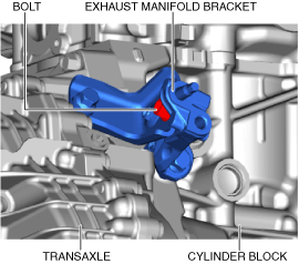
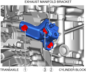
6. Remove the exhaust manifold bracket using the following procedure:
ac5uuw00006893
|
ac5uuw00006895
|
ac5uuw00006897
|
ac5uuw00006893
|
ac5uuw00006899
|
7. Remove the bracket No.1 (drive shaft bracket). (See FRONT DRIVE SHAFT REMOVAL/INSTALLATION.)
8. Remove the starter. (See STARTER REMOVAL/INSTALLATION [SKYACTIV-G 2.5 (WITH CYLINDER DEACTIVATION)].)
9. Remove the coolant control valve. (See COOLANT CONTROL VALVE REMOVAL/INSTALLATION [SKYACTIV-G 2.5 (WITH CYLINDER DEACTIVATION)].)
10. Fix the drive plate using the crankshaft pulley lock bolt.
11. Remove the torque converter installation nut from the starter installation hole. (See AUTOMATIC TRANSAXLE REMOVAL/INSTALLATION [FW6A-EL].)
12. Disconnect the engine and transaxle, and lower only the engine from the engine lifter. (See AUTOMATIC TRANSAXLE REMOVAL/INSTALLATION [FW6A-EL].)
13. Remove the generator. (See GENERATOR REMOVAL/INSTALLATION [SKYACTIV-G 2.5 (WITH CYLINDER DEACTIVATION)].)
14. Remove the intake-air system. (See INTAKE-AIR SYSTEM REMOVAL/INSTALLATION [SKYACTIV-G 2.5 (WITH CYLINDER DEACTIVATION)].)
15. Remove the oil separator. (See POSITIVE CRANKCASE VENTILATION (PCV) VALVE REMOVAL/INSTALLATION [SKYACTIV-G 2.5 (WITH CYLINDER DEACTIVATION)].)
16. Remove the knock sensor (KS). (See KNOCK SENSOR (KS) REMOVAL/INSTALLATION [SKYACTIV-G 2.5 (WITH CYLINDER DEACTIVATION)].)
17. Remove the fuel injectors. (See FUEL INJECTOR REMOVAL/INSTALLATION [SKYACTIV-G 2.5 (WITH CYLINDER DEACTIVATION)].)
18. Remove the camshaft position (CMP) sensor. (See CAMSHAFT POSITION (CMP) SENSOR REMOVAL/INSTALLATION [SKYACTIV-G 2.5 (WITH CYLINDER DEACTIVATION)].)
19. Remove the vacuum pump. (See VACUUM PUMP REMOVAL/INSTALLATION [SKYACTIV-G 2.5 (WITH CYLINDER DEACTIVATION)].)
20. Remove the high pressure fuel pump and rear housing. (See HIGH PRESSURE FUEL PUMP REMOVAL/INSTALLATION [SKYACTIV-G 2.5 (WITH CYLINDER DEACTIVATION)].)
21. Remove the electric variable valve timing motor/driver. (See ELECTRIC VARIABLE VALVE TIMING MOTOR/DRIVER REMOVAL/INSTALLATION [SKYACTIV-G 2.5 (WITH CYLINDER DEACTIVATION)].)
22. Remove the OCV for No.1 cylinder deactivation. (See OIL CONTROL VALVE (OCV) FOR CYLINDER DEACTIVATION REMOVAL/INSTALLATION [SKYACTIV-G 2.5 (WITH CYLINDER DEACTIVATION)].)
23. Remove the OCV for No.4 cylinder deactivation. (See OIL CONTROL VALVE (OCV) FOR CYLINDER DEACTIVATION REMOVAL/INSTALLATION [SKYACTIV-G 2.5 (WITH CYLINDER DEACTIVATION)].)
24. Remove the oil filter. (See OIL FILTER REPLACEMENT [SKYACTIV-G 2.5 (WITH CYLINDER DEACTIVATION)].)
25. Remove the engine oil solenoid valve. (See ENGINE OIL SOLENOID VALVE REMOVAL/INSTALLATION [SKYACTIV-G 2.5 (WITH CYLINDER DEACTIVATION)].)
26. Remove the engine oil temperature sensor/engine oil pressure sensor. (See ENGINE OIL TEMPERATURE SENSOR/ENGINE OIL PRESSURE SENSOR REMOVAL/INSTALLATION [SKYACTIV-G 2.5 (WITH CYLINDER DEACTIVATION)].)
27. Remove the crankshaft position (CKP) sensor. (See CRANKSHAFT POSITION (CKP) SENSOR REMOVAL/INSTALLATION [SKYACTIV-G 2.5 (WITH CYLINDER DEACTIVATION)].)
28. Remove the dipstick.
29. Remove the purge solenoid valve, catch tank and bracket as a single unit. (See PURGE SOLENOID VALVE REMOVAL/INSTALLATION [SKYACTIV-G 2.5 (WITH CYLINDER DEACTIVATION)].)
30. Remove the ignition coil/ion sensors. (See IGNITION COIL/ION SENSOR REMOVAL/INSTALLATION [SKYACTIV-G 2.5 (WITH CYLINDER DEACTIVATION)].)
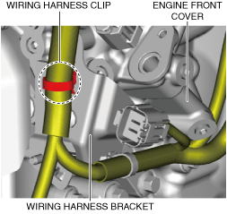
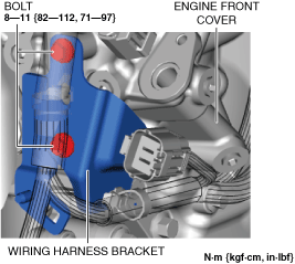
31. Remove the wiring harness bracket using the following procedure:
ac5wzw00010782
|
ac5wzw00010783
|
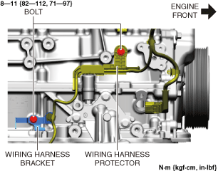
32. Remove the wiring harness bracket and wiring harness protector shown in the figure.
am6xuw00010481
|
33. Remove the emission harness.
34. Remove the water pump drive belt. (See DRIVE BELT REMOVAL/INSTALLATION [SKYACTIV-G 2.5 (WITH CYLINDER DEACTIVATION)].)
35. Remove the water inlet pipe and flange component. (See CYLINDER HEAD GASKET REPLACEMENT [SKYACTIV-G 2.5 (WITH CYLINDER DEACTIVATION)].)
36. Remove the water pump. (See WATER PUMP REMOVAL/INSTALLATION [SKYACTIV-G 2.5 (WITH CYLINDER DEACTIVATION)].)
37. Remove the short cord of the engine oil level sensor. (See ENGINE OIL LEVEL SENSOR REMOVAL/INSTALLATION [SKYACTIV-G 2.5 (WITH CYLINDER DEACTIVATION)].)
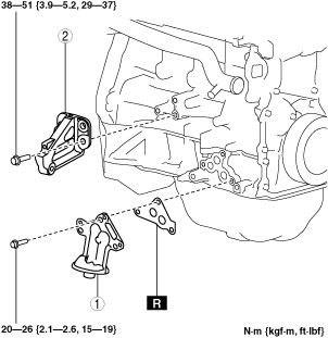
38. Remove in the order indicated in the table.
39. Assemble in the reverse order of disassembly.
am6xuw00005371
|
|
1
|
Oil filter body
|
|
2
|
Exhaust manifold bracket
|
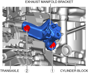
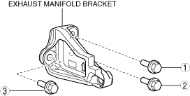
Exhaust Manifold Bracket Installation Note
1. Temporarily tighten the exhaust manifold bracket installation bolts.
2. Tighten the bolt in the order shown in the figure.
ac5uuw00006901
|
Oil Filter Body Installation Note
1. After tightening the three bolts, tighten the first tightened bolt to the specified tightening torque again.