 |
ac5wzw00010929
OCV FOR HYDRAULIC VARIABLE VALVE TIMING SYSTEM INSPECTION [SKYACTIV-G 2.5 (WITH CYLINDER DEACTIVATION)]
id0110s8809800
Coil resistance inspection
1. Disconnect the negative battery terminal. (See NEGATIVE BATTERY TERMINAL DISCONNECTION/CONNECTION.)
2. Remove the plug hole plate. (See PLUG HOLE PLATE REMOVAL/INSTALLATION [SKYACTIV-G 2.5 (WITH CYLINDER DEACTIVATION)].)
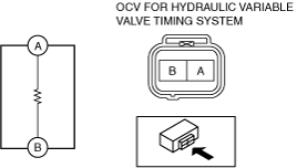
3. Disconnect the OCV for hydraulic variable valve timing system connector.
4. Measure the resistance between terminals A and B using an ohmmeter.
ac5wzw00010929
|
5. Install in the reverse order of removal.
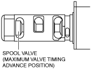
Spool valve operation inspection
1. Disconnect the negative battery terminal. (See NEGATIVE BATTERY TERMINAL DISCONNECTION/CONNECTION.)
2. Remove the OCV for hydraulic variable valve timing system. (See OCV FOR HYDRAULIC VARIABLE VALVE TIMING SYSTEM REMOVAL/INSTALLATION [SKYACTIV-G 2.5 (WITH CYLINDER DEACTIVATION)].)
3. Verify that the spool valve in the OCV for hydraulic variable valve timing system is in the maximum valve timing advance position as indicated in the figure.
ac5wzw00003200
|
4. Verify that the battery is fully charged. (See BATTERY INSPECTION.)
ac5wzw00010929
|
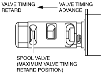
5. Apply battery positive voltage between the OCV for hydraulic variable valve timing system terminals and verify that the spool valve operates and moves to the maximum valve timing retard position.
ac5wzw00003201
|
6. Stop applying battery positive voltage and verify that the spool valve returns to the maximum valve timing advance position.
7. Install the OCV for hydraulic variable valve timing system. (See OCV FOR HYDRAULIC VARIABLE VALVE TIMING SYSTEM REMOVAL/INSTALLATION [SKYACTIV-G 2.5 (WITH CYLINDER DEACTIVATION)].)