 |
ac5uuw00007943
OIL CONTROL VALVE (OCV) INSPECTION [SKYACTIV-G 2.0, SKYACTIV-G 2.5 (WITHOUT CYLINDER DEACTIVATION)]
id0110s9801400
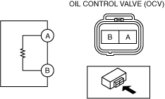
Coil Resistance Inspection
1. Disconnect the negative battery terminal. (See NEGATIVE BATTERY TERMINAL DISCONNECTION/CONNECTION.)
2. Remove the plug hole plate. (See PLUG HOLE PLATE REMOVAL/INSTALLATION [SKYACTIV-G 2.0, SKYACTIV-G 2.5 (WITHOUT CYLINDER DEACTIVATION)].)
3. Disconnect the OCV connector.
4. Measure the resistance between terminals A and B using an ohmmeter.
ac5uuw00007943
|
5. Install in the reverse order of removal.
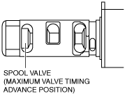
Spool Valve Operation Inspection
1. Disconnect the negative battery terminal. (See NEGATIVE BATTERY TERMINAL DISCONNECTION/CONNECTION.)
2. Remove the OCV. (See OIL CONTROL VALVE (OCV) REMOVAL/INSTALLATION [SKYACTIV-G 2.0, SKYACTIV-G 2.5 (WITHOUT CYLINDER DEACTIVATION)].)
3. Verify that the spool valve in the OCV is in the maximum valve timing advance position as indicated in the figure.
ac5wzw00003200
|
4. Verify that the battery is fully charged. (See BATTERY INSPECTION.)
ac5uuw00007943
|
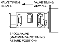
5. Apply battery positive voltage between the OCV terminals and verify that the spool valve operates and moves to the maximum valve timing retard position.
ac5wzw00003201
|
6. Stop applying battery positive voltage and verify that the spool valve returns to the maximum valve timing advance position.
7. Install the OCV. (See OIL CONTROL VALVE (OCV) REMOVAL/INSTALLATION [SKYACTIV-G 2.0, SKYACTIV-G 2.5 (WITHOUT CYLINDER DEACTIVATION)].)