 |
ac8wzw00002655
TURBOCHARGER REMOVAL/INSTALLATION [SKYACTIV-D 2.2]
id0113z7705800
Replacement Part
|
Stud
Quantity: 3
Location of use: Turbocharger
|
Gasket
Quantity: 1
Location of use: Oil pipe No.3
|
Gasket
Quantity: 1
Location of use: Oil pipe No.4
|
|
Gasket
Quantity: 1
Location of use: Turbocharger air inlet pipe
|
Nut
Quantity: 3
Location of use: Turbocharger
|
Gasket
Quantity: 1
Location of use: Turbocharger
|
|
Gasket
Quantity: 1
Location of use: Oil pipe No.5
|
Gasket
Quantity: 2
Location of use: Oil pipe No.1
|
Gasket
Quantity: 2
Location of use: Oil pipe No.2
|
|
Vacuum hose No.1
Quantity: 1
Location of use: MAP sensor No.1
|
—
|
—
|
Operation After Replacing or Removal/Installation Turbocharger
1. If the turbocharger is replaced or removed/installed, perform the following procedure.
|
STEP |
ACTION |
PAGE/CONDITION |
|---|---|---|
|
1
|
Switch the ignition ON (engine off).
|
—
|
|
2
|
Perform KOEO self-test procedure.
|
|
|
3
|
Perform KOER self-test procedure.
|
Turbocharger Removal/Installation
1. Disconnect the negative battery terminal. (See NEGATIVE BATTERY TERMINAL DISCONNECTION/CONNECTION.)
2. Remove the engine cover. (See ENGINE COVER REMOVAL/INSTALLATION [SKYACTIV-D 2.2].)
3. Drain the engine coolant. (See ENGINE COOLANT REPLACEMENT [SKYACTIV-D 2.2].)
4. Remove the air cleaner. (See INTAKE-AIR SYSTEM REMOVAL/INSTALLATION [SKYACTIV-D 2.2].)
5. Remove the battery and the battery tray. (See BATTERY REMOVAL/INSTALLATION [SKYACTIV-D 2.2].)
6. Remove the following parts as a single unit: (See INTAKE-AIR SYSTEM REMOVAL/INSTALLATION [SKYACTIV-D 2.2].)
7. Remove the nuts and set the turbocharger air outlet pipe component aside. (See INTAKE-AIR SYSTEM REMOVAL/INSTALLATION [SKYACTIV-D 2.2].)
ac8wzw00002655
|
8. Disconnect the blow-by heater connector. (See INTAKE-AIR SYSTEM REMOVAL/INSTALLATION [SKYACTIV-D 2.2].)
9. Disconnect the breather hose from the blow-by heater side. (See INTAKE-AIR SYSTEM REMOVAL/INSTALLATION [SKYACTIV-D 2.2].)
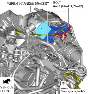
10. Remove the bolts shown in the figure and set aside the wiring harness bracket and wiring harness as a single unit.
ac8wzw00002656
|
11. Disconnect the MAP sensor No.1 connector. (See MANIFOLD ABSOLUTE PRESSURE (MAP) SENSOR REMOVAL/INSTALLATION [SKYACTIV-D 2.2].)
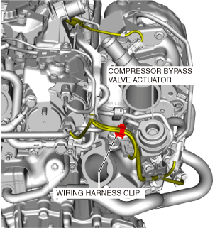
12. Disconnect the wiring harness clips shown in the figure.
ac8wzw00002657
|
13. Disconnect the Variable turbine geometry turbocharger actuator mid-connector.
ac8wzw00002658
|
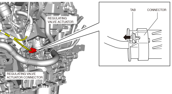
14. Disconnect the regulating valve actuator connector using the following procedure.
ac8wzw00002659
|
15. Remove the bolts shown in the figure and set aside the wiring harness bracket and wiring harness as a single unit.
ac8wzw00002660
|
16. Disconnect the vacuum hose as shown in the figure.
ac8wzw00002661
|
17. Remove the front crossmember. (See FRONT CROSSMEMBER REMOVAL/INSTALLATION.)
18. Remove the catalytic converter. (See EXHAUST SYSTEM REMOVAL/INSTALLATION [SKYACTIV-D 2.2].)
19. Remove the transfer. (4WD)(See TRANSFER REMOVAL/INSTALLATION [GW6AX-EL].)
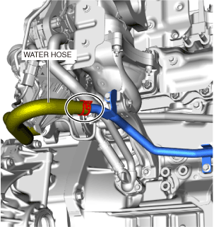
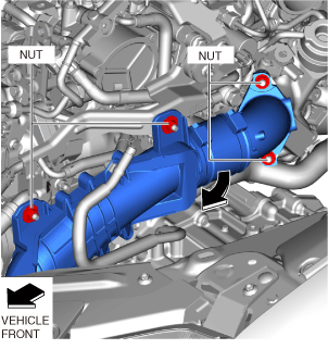
20. Disconnect the water hose as shown in the figure.
ac8wzw00002662
|
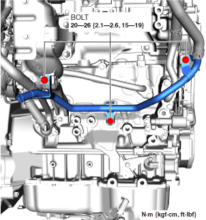
21. Remove the bolts shown in the figure and set aside the water pipe.
ac8wzw00002663
|
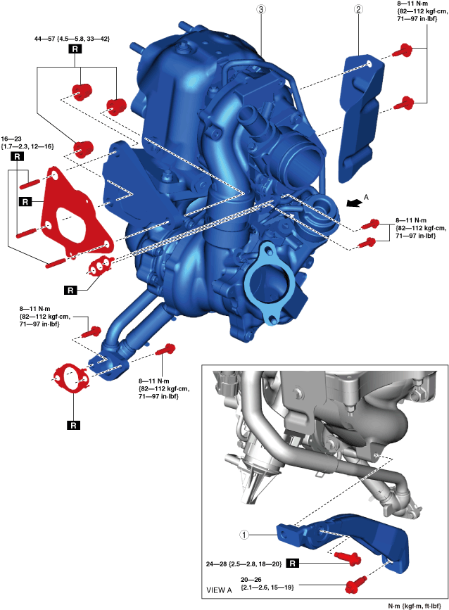
22. Remove in the order shown in the figure.
23. Install in the reverse order of removal.
24. Refill the engine coolant. (See ENGINE COOLANT REPLACEMENT [SKYACTIV-D 2.2].)
25. Perform the following procedure.
Step 1
am6zzw00018162
|
|
1
|
Turbocharger bracket
|
|
2
|
Turbocharger insulator No.1
|
|
3
|
Turbocharger component
|
Step 2
am6zzw00018536
|
|
1
|
Turbocharger air inlet pipe
|
|
2
|
Turbocharger insulator No.2
|
|
3
|
Turbocharger insulator No.3
|
|
4
|
Oil pipe No.1
|
|
5
|
Oil pipe No.2
|
|
6
|
Oil pipe No.3
|
|
7
|
Oil hose No.1
|
|
8
|
Oil pipe No.4
|
|
9
|
Oil hose No.2
|
|
10
|
Oil pipe No.5
|
|
11
|
Vacuum hose No.1
|
|
12
|
Vacuum hose No.2
|
|
13
|
MAP sensor No.1
|
|
14
|
Variable turbine geometry turbocharger actuator connector
|
|
15
|
Turbocharger
|
Vacuum hose No.2 installation note
1. Install the vacuum hose No.2 as shown in the figure.
ac8wzw00002666
|
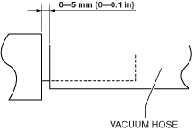
Vacuum hose No.1 installation note
1. Install the vacuum hose No.1 as shown in the figure.
ac8wzw00002667
|
Oil hose No.2 installation note
1. Install the oil hose No.2 as shown in the figure.
ac8wzw00002668
|
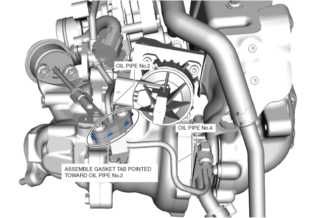
Oil pipe No.4 installation note
1. Temporarily tighten bolts (1), and (2) shown in the figure.
ac8wzw00002669
|
2. Tighten bolt (1).
3. Tighten bolt (2).
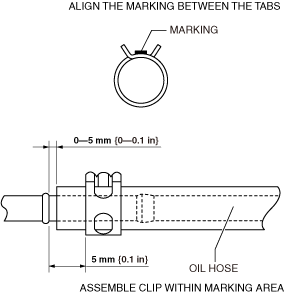
Oil hose No.1 installation note
1. Install the Oil hose No.1 as shown in the figure.
Oil pipe No.4 side
ac8wzw00002670
|
Oil pipe No.3 side
ac8wzw00002671
|
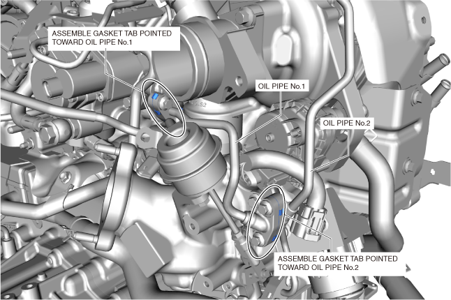
Oil pipe No.2 installation note
1. Install the gasket as shown in the figure.
ac8wzw00002672
|
2. Temporarily tighten bolts (1), (2), and (3) shown in the figure.
ac8wzw00002673
|
3. Tighten bolts (1) and (2).
4. Tighten bolt (3).
Oil pipe No.1 installation note
1. Install the gaskets as shown in the figure.
ac8wzw00002674
|
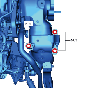
Turbocharger component installation note
1. Install the new stud bolts to the exhaust manifold.
2. Tighten the nuts shown in the figure to the specified torque.
ac8wzw00002675
|
3. Tighten the nut to the specified torque again.