 |
ac5wzw00011272
INTAKE AIR TEMPERATURE (IAT) SENSOR INSPECTION [SKYACTIV-G 2.0, SKYACTIV-G 2.5 (WITHOUT CYLINDER DEACTIVATION)]
id0140h4802200
IAT Sensor No.1
Function inspection
1. Connect the M-MDS to the DLC-2.
2. Switch the ignition ON (engine off).
3. Display the PID IAT. (See ON-BOARD DIAGNOSTIC TEST [PCM (SKYACTIV-G 2.0, SKYACTIV-G 2.5 (WITHOUT CYLINDER DEACTIVATION))].) (See PCM INSPECTION [SKYACTIV-G 2.0, SKYACTIV-G 2.5 (WITHOUT CYLINDER DEACTIVATION)].)
4. Compare the voltage and temperature indications for the PID IAT with the standard in the table indicated below.
Standard
|
IAT |
|
|---|---|
|
V |
°C {°F} |
|
Approx. 2.70
|
20 {68}
|
|
Approx. 1.80
|
40 {104}
|
|
Approx. 1.20
|
60 {140}
|
IAT Sensor No.2
Function Inspection
1. Connect the M-MDS to the DLC-2.
2. Switch the ignition ON (engine off).
3. Display the PID IAT2. (See ON-BOARD DIAGNOSTIC TEST [PCM (SKYACTIV-G 2.0, SKYACTIV-G 2.5 (WITHOUT CYLINDER DEACTIVATION))].) (See PCM INSPECTION [SKYACTIV-G 2.0, SKYACTIV-G 2.5 (WITHOUT CYLINDER DEACTIVATION)].)
4. Compare the voltage and temperature indications for the PID IAT2 with the standard in the table indicated below.
Standard
|
IAT2 |
|
|---|---|
|
V |
°C {°F} |
|
Approx. 3.57
|
20 {68}
|
|
Approx. 2.70
|
40 {104}
|
|
Approx. 1.87
|
60 {140}
|
Resistance inspection
1. Disconnect the negative battery terminal. (See NEGATIVE BATTERY TERMINAL DISCONNECTION/CONNECTION.)
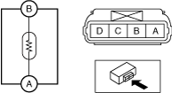
2. Disconnect the MAP sensor/IAT sensor No.2 connector.
3. Remove the MAP sensor/IAT sensor No.2. (See MANIFOLD ABSOLUTE PRESSURE (MAP) SENSOR/INTAKE AIR TEMPERATURE (IAT) SENSOR NO.2 REMOVAL/INSTALLATION [SKYACTIV-G 2.0, SKYACTIV-G 2.5 (WITHOUT CYLINDER DEACTIVATION)].)
4. Measure the resistance between MAP sensor/IAT sensor No.2 terminals A and B.
ac5wzw00011272
|
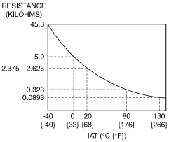
Specification
|
IAT2 (°C {°F}) |
Resistance (Kilohms) |
|---|---|
|
0 {32}
|
Approx. 5.9
|
|
20 {68}
|
2.375—2.625
|
|
80 {176}
|
Approx. 0.323
|
|
130 {266}
|
Approx. 0.0893
|
ac5uuw00003033
|