|
am6zzw00012042
PCM INSPECTION [SKYACTIV-D 2.2]
id0140z7802500
Without Using the M-MDS
Terminal Voltage Table (Reference)
am6zzw00012042
|
|
Terminal |
Signal |
Connected to |
Test condition |
Voltage (V) |
inspection item |
|
|---|---|---|---|---|---|---|
|
1A
|
CMP (G+)
|
CMP sensor
|
• CMP sensor
• Related wiring harness
|
|||
|
1B
|
CMP (G–)
|
CMP sensor
|
Switch the ignition ON (engine off)
|
Below 1.0
|
• CMP sensor
• Related wiring harness
|
|
|
1C
|
Coolant control valve position
|
Coolant control valve position sensor
|
Because this terminal is for communication, integrity determination using terminal voltage inspection is not possible.
|
• Coolant control valve
• Related wiring harness
|
||
|
1D*4
|
Generator output voltage
|
Generator
|
(See CKP (NE+) signal.)
|
• Generator
• Related wiring harness
|
||
|
1E
|
CKP (NE+)
|
CKP sensor
|
• CKP sensor
• Related wiring harness
|
|||
|
1F
|
CKP (NE–)
|
CKP sensor
|
Switch the ignition ON (engine off)
|
Below 1.0
|
• CKP sensor
• Related wiring harness
|
|
|
1G
|
GND
|
Sensor shield
|
Switch the ignition ON (engine off)
|
Below 1.0
|
• Related wiring harness
|
|
|
1H
|
A/F (+)
|
A/F sensor
|
Idle (after warm up)
|
Approx. 2.85
|
• A/F sensor
• Related wiring harness
|
|
|
1I
|
A/F (−)
|
A/F sensor
|
Idle (after warm up)
|
Approx. 2.35
|
• A/F sensor
• Related wiring harness
|
|
|
1J
|
Constant voltage (Vref)
|
CKP sensor
|
Switch the ignition ON (engine off)
|
Approx. 4.99
|
• Related wiring harness
|
|
|
1K
|
Constant voltage (Vref)
|
CMP sensor
|
Switch the ignition ON (engine off)
|
Approx. 4.99
|
• Related wiring harness
|
|
|
1L
|
GND
|
Engine oil level sensor
|
Switch ignition ON (engine off)
|
Below 1.0
|
• Related wiring harness
|
|
|
1M
|
Constant voltage (Vref)
|
Fuel pressure sensor (in fuel injector No.1)
|
Switch ignition ON (engine off)
|
Approx. 4.99
|
• Related wiring harness
|
|
|
1N
|
Constant voltage (Vref)
|
Fuel pressure sensor (in fuel injector No.4)
|
Switch ignition ON (engine off)
|
Approx. 4.99
|
• Related wiring harness
|
|
|
1O
|
—
|
—
|
—
|
—
|
—
|
|
|
1P
|
LIN
|
Fuel temperature sensor (in fuel injector No.3)
|
Because this terminal is for communication, integrity determination using terminal voltage inspection is not possible.
|
• Related wiring harness
|
||
|
1Q
|
GND
|
EGR valve position sensor
|
Switch the ignition ON (engine off)
|
Below 1.0
|
• Related wiring harness
|
|
|
1R
|
GND
|
Fuel pressure sensor (in fuel injector No.1)
|
Switch ignition ON (engine off)
|
Below 1.0
|
• Related wiring harness
|
|
|
1S
|
GND
|
Fuel pressure sensor (in fuel injector No.4)
|
Switch ignition ON (engine off)
|
Below 1.0
|
• Related wiring harness
|
|
|
1T
|
LIN
|
Fuel temperature sensor (in fuel injector No.1)
|
Because this terminal is for communication, integrity determination using terminal voltage inspection is not possible.
|
• Related wiring harness
|
||
|
1U
|
LIN
|
Fuel temperature sensor (in fuel injector No.4)
|
Because this terminal is for communication, integrity determination using terminal voltage inspection is not possible.
|
• Related wiring harness
|
||
|
1V
|
LIN
|
Fuel temperature sensor (in fuel injector No.2)
|
Because this terminal is for communication, integrity determination using terminal voltage inspection is not possible.
|
• Related wiring harness
|
||
|
1W
|
—
|
—
|
—
|
—
|
—
|
|
|
1X
|
—
|
—
|
—
|
—
|
—
|
|
|
1Y*1
|
CAN_2L
|
CAN system related modules
|
Because this terminal is for CAN, good/no good judgment by terminal voltage is not possible.
|
• Related wiring harness
|
||
|
1Z
|
Exhaust gas pressure
|
Exhaust gas pressure sensor No.2
|
Switch the ignition ON (engine off)
|
Approx. 0.487
|
• Exhaust gas pressure sensor No.2
• Related wiring harness
|
|
|
Idle (after warm up)
|
0.580—0.750
|
|||||
|
1AA
|
—
|
—
|
—
|
—
|
—
|
|
|
1AB*6
|
EGR temperature
|
EGR temperature sensor
|
Switch the ignition ON (engine off)
|
Approx. 5.03
|
• EGR temperature sensor
• Related wiring harness
|
|
|
1AC
|
GND
|
Exhaust gas temperature sensor No.1
|
Switch the ignition ON (engine off)
|
Below 1.0
|
• Related wiring harness
|
|
|
1AD*1
|
CAN_2H
|
CAN system related modules
|
Because this terminal is for CAN, good/no good judgment by terminal voltage is not possible.
|
• Related wiring harness
|
||
|
1AE
|
GND
|
Exhaust gas pressure sensor No.2
|
Switch the ignition ON (engine off)
|
Below 1.0
|
• Related wiring harness
|
|
|
1AF
|
GND
|
Sensor shield
|
Switch the ignition ON (engine off)
|
Below 1.0
|
• Related wiring harness
|
|
|
1AG
|
Fuel pressure No.1
|
Fuel pressure sensor (in fuel injector No.1)
|
Switch the ignition ON (engine off)}
|
Approx. 0.950
|
• Fuel pressure sensor (in fuel injector No.1)
• Related wiring harness
|
|
|
Idle (after warm up)
|
Approx. 1.103—1.293
|
|||||
|
1AH
|
GND
|
IAT sensor No.2
|
Switch the ignition ON (engine off)
|
Below 1.0
|
• Related wiring harness
|
|
|
1AI
|
—
|
—
|
—
|
—
|
—
|
|
|
1AJ
|
Coolant control valve (3WAY−)
|
Coolant control valve
|
Switch ignition ON (engine off)
|
Approx. 12.72
|
• Coolant control valve
• Related wiring harness
|
|
|
Idle (when cold)
|
Approx. 14.34
|
|||||
|
Idle (after warm up)
|
Approx. 14.33
|
|||||
|
1AK
|
Constant voltage (Vref)
|
Exhaust gas pressure sensor No.2
|
Switch the ignition ON (engine off)
|
Approx. 4.99
|
• Related wiring harness
|
|
|
1AL
|
—
|
—
|
—
|
—
|
—
|
|
|
1AM
|
Fuel pressure No.3
|
Fuel pressure sensor (in fuel injector No.3)
|
Switch the ignition ON (engine off)}
|
Approx. 0.950
|
• Fuel pressure sensor (in fuel injector No.3)
• Related wiring harness
|
|
|
Idle (after warm up)
|
Approx. 1.8—2.4
|
|||||
|
1AN
|
—
|
—
|
—
|
—
|
—
|
|
|
1AO
|
Coolant control valve (3WAY+)
|
Coolant control valve
|
Switch ignition ON (engine off)
|
Approx. 12.68
|
• Coolant control valve
• Related wiring harness
|
|
|
1AP
|
Constant voltage (Vref)
|
EGR valve position sensor
|
Switch the ignition ON (engine off)
|
Approx. 4.99
|
• Related wiring harness
|
|
|
1AQ
|
EGR valve position
|
EGR valve position sensor
|
Switch the ignition ON (engine off)
|
Approx. 1.236
|
• EGR valve position sensor
• Related wiring harness
|
|
|
Idle (after warm up)
|
1.210—1.490
|
|||||
|
1AR
|
—
|
—
|
—
|
—
|
—
|
|
|
1AS
|
Intake shutter valve (ISV+)
|
Intake shutter valve
|
Switch the ignition ON (engine off)
|
Approx. 12.10
|
• Intake shutter valve
• Related wiring harness
|
|
|
Idle
|
Approx. 14.15
|
|||||
|
1AT
|
GND
|
EGR cooler bypass valve position sensor
|
Switch the ignition ON (engine off)
|
Below 1.0
|
• Related wiring harness
|
|
|
1AU
|
Constant voltage (Vref)
|
EGR cooler bypass valve position sensor
|
Switch the ignition ON (engine off)
|
Approx. 4.99
|
• Related wiring harness
|
|
|
1AV
|
EGR cooler bypass valve position
|
EGR cooler bypass valve position sensor
|
Switch the ignition ON (engine off)
|
Below 1.0
|
• EGR cooler bypass valve position sensor
• Related wiring harness
|
|
|
Idle (after warm up)
|
1.210—1.380
|
|||||
|
1AW
|
GND
|
Sensor shield
|
Switch the ignition ON (engine off)
|
Below 1.0
|
• Related wiring harness
|
|
|
1AX
|
Intake shutter valve (ISV−)
|
Intake shutter valve
|
Switch the ignition ON (engine off)
|
Approx. 12.10
|
• Intake shutter valve
• Related wiring harness
|
|
|
1AY
|
GND
|
Intake shutter valve position sensor
|
Switch the ignition ON (engine off)
|
Below 1.0
|
• Related wiring harness
|
|
|
1AZ
|
Constant voltage (Vref)
|
Intake shutter valve position sensor
|
Switch the ignition ON (engine off)
|
Approx. 4.99
|
• Related wiring harness
|
|
|
1BA
|
Intake shutter valve position
|
Intake shutter valve position sensor
|
Switch the ignition ON (engine off)
|
Approx. 4.28
|
• Intake shutter valve position sensor
• Related wiring harness
|
|
|
Idle (after warm up)
|
Approx. 0.20—0.58
|
|||||
|
1BB
|
—
|
—
|
—
|
—
|
—
|
|
|
1BC
|
EGR cooler bypass valve (−) (EGR−)
|
EGR cooler bypass valve
|
Switch the ignition ON (engine off)
|
Approx. 12.10
|
• EGR cooler bypass valve
• Related wiring harness
|
|
|
(See Suction control valve signal.)
|
||||||
|
1BD
|
GND
|
Variable turbine geometry turbocharger actuator position sensor
|
Switch ignition ON (engine off)
|
Below 1.0
|
• Related wiring harness
|
|
|
1BE
|
Constant voltage (Vref)
|
Variable turbine geometry turbocharger actuator position sensor
|
Switch ignition ON (engine off)
|
Approx. 4.99
|
• Variable turbine geometry turbocharger actuator position sensor
• Related wiring harness
|
|
|
1BF
|
—
|
—
|
—
|
—
|
—
|
|
|
1BG
|
Fuel pressure No.4
|
Fuel pressure sensor (in fuel injector No.4)
|
Switch the ignition ON (engine off)
|
Approx. 0.950
|
• Fuel pressure sensor (in fuel injector No.4)
• Related wiring harness
|
|
|
Idle (after warm up)
|
Approx. 0.6—1.4
|
|||||
|
1BH
|
EGR cooler bypass valve (+) (EGR+)
|
EGR cooler bypass valve
|
Switch the ignition ON (engine off)
|
Approx. 12.10
|
• EGR cooler bypass valve
• Related wiring harness
|
|
|
Idle
|
Approx. 12.10
|
|||||
|
1BI
|
GND
|
MAP sensor No.1
|
Switch the ignition ON (engine off)
|
Below 1.0
|
• Related wiring harness
|
|
|
1BJ
|
Constant voltage (Vref)
|
MAP sensor No.1
|
Switch the ignition ON (engine off)
|
Approx. 4.99
|
• Related wiring harness
|
|
|
1BK
|
MAP
|
MAP sensor No.1
|
Switch the ignition ON (engine off)
|
Approx. 1.172
|
• MAP sensor No.1
• Related wiring harness
|
|
|
Idle (after warm up)
|
1.235—1.49
|
|||||
|
1BL
|
Fuel pressure No.2
|
Fuel pressure sensor (in fuel injector No.2)
|
Switch the ignition ON (engine off)
|
Approx. 0.950
|
• Fuel pressure sensor (in fuel injector No.2)
• Related wiring harness
|
|
|
Idle (after warm up)
|
Approx. 0.56—1.3
|
|||||
|
1BM
|
EGR valve (EGR−)
|
EGR valve
|
Switch the ignition ON (engine off)
|
Approx. 12.09
|
• EGR valve
• Related wiring harness
|
|
|
Idle (when cold)
|
Approx. 12.09
|
|||||
|
Idle (after warm up)
|
Approx. 13.08
|
|||||
|
1BN
|
GND
|
Coolant control valve position sensor
|
Switch ignition ON (engine off)
|
Below 1.0
|
• Related wiring harness
|
|
|
1BO
|
Constant voltage (Vref)
|
Coolant control valve position sensor
|
Switch ignition ON (engine off)
|
Approx. 4.99
|
• Related wiring harness
|
|
|
1BP
|
Variable turbine geometry turbocharger actuator position
|
Variable turbine geometry turbocharger actuator position sensor
|
Switch ignition ON (engine off)
|
Approx. 0.874
|
• Variable turbine geometry turbocharger actuator position sensor
• Related wiring harness
|
|
|
Idle (after warm up)
|
Approx. 4.410
|
|||||
|
1BQ
|
GND
|
Fuel pressure sensor (in fuel injector No.3)
|
Switch the ignition ON (engine off)
|
Below 1.0
|
• Related wiring harness
|
|
|
1BR
|
EGR valve (EGR+)
|
EGR valve
|
Switch the ignition ON (engine off)
|
Approx. 12.09
|
• EGR valve
• Related wiring harness
|
|
|
1BS
|
GND
|
Exhaust gas temperature sensor No.3
|
Under any condition
|
Below 1.0
|
• Related wiring harness
|
|
|
1BT
|
—
|
—
|
—
|
—
|
—
|
|
|
1BU
|
—
|
—
|
—
|
—
|
—
|
|
|
1BV
|
Constant voltage (Vref)
|
Fuel pressure sensor (in fuel injector No.3)
|
Switch the ignition ON (engine off)
|
Approx. 4.99
|
• Related wiring harness
|
|
|
1BW
|
Exhaust gas temperature
|
Exhaust gas temperature sensor No.3
|
Switch the ignition ON (engine off)
|
Approx. 2.29
|
• Exhaust gas temperature sensor No.3
• Related wiring harness
|
|
|
1BX
|
Constant voltage (Vref)
|
Fuel pressure sensor (in fuel injector No.2)
|
Switch the ignition ON (engine off)
|
Approx. 4.99
|
• Related wiring harness
|
|
|
1BY
|
Suction control valve
|
Suction control valve
|
Switch the ignition ON (engine off)
|
Below 1.0
|
• Suction control valve
• Related wiring harness
|
|
|
1BZ
|
Variable turbine geometry turbocharger actuator (TCV2-)
|
Variable turbine geometry turbocharger actuator
|
Switch the ignition ON (engine off)
|
Below 1.0
|
• Variable turbine geometry turbocharger actuator
• Related wiring harness
|
|
|
1CA
|
Exhaust gas temperature
|
Exhaust gas temperature sensor No.2
|
Switch the ignition ON (engine off)
|
Approx. 2.33
|
• Exhaust gas temperature sensor No.2
• Related wiring harness
|
|
|
1CB
|
GND
|
Exhaust gas temperature sensor No.2
|
Switch the ignition ON (engine off)
|
Below 1.0
|
• Related wiring harness
|
|
|
1CC
|
Suction control valve
|
Suction control valve
|
Switch the ignition ON (engine off)
|
Below 1.0
|
• Suction control valve
• Related wiring harness
|
|
|
1CD
|
Variable turbine geometry turbocharger actuator (TCV2+)
|
Variable turbine geometry turbocharger actuator
|
Switch the ignition ON (engine off)
|
B+
|
• Variable turbine geometry turbocharger actuator
• Related wiring harness
|
|
|
Idle (after warm up)
|
B+
|
|||||
|
1CE
|
Exhaust gas pressure
|
Exhaust gas pressure sensor No.1
|
Switch the ignition ON (engine off)
|
Approx. 0.957
|
• Exhaust gas pressure sensor No.1
• Related wiring harness
|
|
|
Idle (after warm up)
|
0.975—1.230
|
|||||
|
1CF
|
GND
|
Exhaust gas pressure sensor No.1
|
Switch the ignition ON (engine off)
|
Below 1.0
|
• Related wiring harness
|
|
|
1CG
|
A/F sensor heater control
|
A/F sensor heater
|
(See Engine oil control signal.)
|
• A/F sensor heater
• Related wiring harness
|
||
|
1CH
|
Engine oil control
|
Engine oil solenoid valve
|
• Engine oil solenoid valve
• Related wiring harness
|
|||
|
1CI
|
Exhaust gas temperature
|
Exhaust gas temperature sensor No.1
|
Switch the ignition ON (engine off)
|
Approx. 0.90
|
• Exhaust gas temperature sensor No.1
• Related wiring harness
|
|
|
1CJ
|
Constant voltage (Vref)
|
Exhaust gas pressure sensor No.1
|
Switch the ignition ON (engine off)
|
Approx. 4.99
|
• Related wiring harness
|
|
|
1CK
|
Regulating valve actuator (TCV1+)
|
Regulating valve actuator
|
Switch the ignition ON (engine off)
|
B+
|
• Regulating valve actuator
• Related wiring harness
|
|
|
Idle (after warm up)
|
B+
|
|||||
|
1CL
|
Regulating valve actuator (TCV1-)
|
Regulating valve actuator
|
• Regulating valve actuator
• Related wiring harness
|
|||
|
1CM
|
IAT (No.2)
|
IAT sensor No.2
|
Switch the ignition ON (engine off)
|
Approx. 3.30
|
• IAT sensor No.2
• Related wiring harness
|
|
|
1CN
|
Constant voltage (Vref)
|
MAP sensor No.2
|
Switch the ignition ON (engine off)
|
Approx. 4.99
|
• Related wiring harness
|
|
|
1CO
|
Compressor bypass solenoid valve
|
Compressor bypass solenoid valve
|
Switch the ignition ON (engine off)
|
B+
|
• Compressor bypass solenoid valve
• Related wiring harness
|
|
|
Racing (Engine speed: 4,000 rpm)
|
Below 1.0
|
|||||
|
1CP
|
—
|
—
|
—
|
—
|
—
|
|
|
1CQ
|
MAP
|
MAP sensor No.2
|
Switch the ignition ON (engine off)
|
Approx. 1.630
|
• MAP sensor No.2
• Related wiring harness
|
|
|
Idle (after warm up)
|
1.380—1.580
|
|||||
|
1CR
|
GND
|
MAP sensor No.2
|
Switch the ignition ON (engine off)
|
Below 1.0
|
• Related wiring harness
|
|
|
1CS
|
Fuel injection control (−)
|
Fuel injector No.3
|
• Fuel injector No.3
• Related wiring harness
|
|||
|
1CT
|
Fuel injection control (−)
|
Fuel injector No.2
|
• Fuel injector No.2
• Related wiring harness
|
|||
|
1CU
|
—
|
—
|
—
|
—
|
—
|
|
|
1CV
|
—
|
—
|
—
|
—
|
—
|
|
|
1CW
|
Fuel injection control (+)
|
Fuel injector No.2
|
• Fuel injector No.2
• Related wiring harness
|
|||
|
1CX
|
—
|
—
|
—
|
—
|
—
|
|
|
1CY
|
—
|
—
|
—
|
—
|
—
|
|
|
1CZ*6
|
GND
|
EGR temperature sensor
|
Switch the ignition ON (engine off)
|
Approx. 0.31
|
• EGR temperature sensor
• Related wiring harness
|
|
|
1DA
|
Fuel injection control (+)
|
Fuel injector No.3
|
• Fuel injector No.3
• Related wiring harness
|
|||
|
1DB
|
—
|
—
|
—
|
—
|
—
|
|
|
1DC
|
ECT
|
ECT sensor
|
Switch the ignition ON (engine off)
|
ECT is 20°C {68°F}
|
Approx. 2.37
|
• ECT sensor
• Related wiring harness
|
|
ECT is 40°C {104°F}
|
Approx. 1.49
|
|||||
|
ECT is 60°C {140°F}
|
Approx. 0.89
|
|||||
|
ECT is 80°C {176°F}
|
Approx. 0.52
|
|||||
|
ECT is 100°C {212°F}
|
Approx. 0.24
|
|||||
|
1DD
|
GND
|
ECT sensor
|
Switch the ignition ON (engine off)
|
Below 1.0
|
• Related wiring harness
|
|
|
1DE
|
Constant voltage (Vref)
|
Regulating valve actuator position sensor
|
Switch the ignition ON (engine off)
|
Approx. 4.99
|
• Related wiring harness
|
|
|
1DF
|
—
|
—
|
—
|
—
|
—
|
|
|
1DG
|
PRD−
|
Fuel pressure relief valve
|
Switch the ignition ON (engine off)
|
Approx. 4.67
|
• Fuel pressure relief valve
• Related wiring harness
|
|
|
Idle (after warm up)
|
Approx. 3.91—4.71
|
|||||
|
1DH
|
Battery voltage
|
Main relay
|
Switch the ignition ON (engine off)
|
B+
|
• Main relay
• Related wiring harness
|
|
|
1DI
|
Engine oil temperature
|
Engine oil temperature sensor
|
Switch the ignition ON (engine off)
|
Approx. 2.92
|
• Engine oil temperature sensor
• Related wiring harness
|
|
|
1DJ
|
GND
|
Engine oil temperature sensor, engine oil pressure sensor
|
Switch the ignition ON (engine off)
|
Below 1.0
|
• Related wiring harness
|
|
|
1DK
|
PRD+
|
Fuel pressure relief valve
|
Switch the ignition ON (engine off)
|
Approx. 4.67
|
• Fuel pressure relief valve
• Related wiring harness
|
|
|
Idle (after warm up)
|
Approx. 3.91—4.71
|
|||||
|
1DL
|
Battery voltage
|
Main relay
|
Switch the ignition ON (engine off)
|
B+
|
• Main relay
• Related wiring harness
|
|
|
1DM
|
Engine oil pressure
|
Engine oil pressure sensor
|
Switch the ignition ON (engine off)
|
Approx. 4.92
|
• Engine oil pressure sensor
• Related wiring harness
|
|
|
Idle (after warm up)
|
Approx. 0.42—1.098
|
|||||
|
1DN
|
Constant voltage (Vref)
|
Engine oil temperature sensor, engine oil pressure sensor
|
Switch the ignition ON (engine off)
|
Approx. 4.99
|
• Related wiring harness
|
|
|
1DO
|
—
|
—
|
—
|
—
|
—
|
|
|
1DP
|
—
|
—
|
—
|
—
|
—
|
|
|
1DQ
|
—
|
—
|
—
|
—
|
—
|
|
|
1DR
|
GND
|
Regulating valve actuator position sensor
|
Switch the ignition ON (engine off)
|
Below 1.0
|
• Related wiring harness
|
|
|
1DS
|
—
|
—
|
—
|
—
|
—
|
|
|
1DT
|
—
|
—
|
—
|
—
|
—
|
|
|
1DU*6
|
Exhaust gas temperature
|
Exhaust gas temperature sensor No.4
|
Switch the ignition ON (engine off)
|
Approx. 0.525
|
• Exhaust gas temperature sensor No.4
• Related wiring harness
|
|
|
Idle (after warm up)
|
0.580—0.750
|
|||||
|
1DV*6
|
GND
|
Exhaust gas temperature sensor No.4
|
Under any condition
|
Approx. 0.01
|
• Related wiring harness
|
|
|
1DW
|
Fuel injection control (+)
|
Fuel injector No.4
|
• Fuel injector No.4
• Related wiring harness
|
|||
|
1DX
|
—
|
—
|
—
|
—
|
—
|
|
|
1DY
|
Regulating valve actuator position
|
Regulating valve actuator position sensor
|
Switch the ignition ON (engine off)
|
Approx. 0.874
|
• Regulating valve actuator position sensor
• Related wiring harness
|
|
|
Idle (after warm up)
|
Approx. 4.410
|
|||||
|
1DZ
|
—
|
—
|
—
|
—
|
—
|
|
|
1EA
|
Fuel injection control (+)
|
Fuel injector No.1
|
• Fuel injector No.1
• Related wiring harness
|
|||
|
1EB
|
GND
|
Sensor shield
|
Switch the ignition ON (engine off)
|
Below 1.0
|
• Related wiring harness
|
|
|
1EC
|
—
|
—
|
—
|
—
|
—
|
|
|
1ED*2
|
Neutral position (sub)
|
Neutral switch No.2
|
Shift lever is at neutral position
|
Below 1.0
|
• Neutral switch No.2
• Related wiring harness
|
|
|
Shift lever is not at neutral position
|
B+
|
|||||
|
1EE
|
Fuel injection control (−)
|
Fuel injector No.1
|
• Fuel injector No.1
• Related wiring harness
|
|||
|
1EF
|
Fuel injection control (−)
|
Fuel injector No.4
|
• Fuel injector No.4
• Related wiring harness
|
|||
|
1EG*2
|
Neutral position
|
Neutral switch No.1
|
Shift lever is at neutral position
|
Below 1.0
|
• Neutral switch No.1
• Related wiring harness
|
|
|
Shift lever is not at neutral position
|
B+
|
|||||
|
1EH*2
|
Back-up light
|
Back-up light switch
|
Shift lever is at R position
|
Below 1.0
|
• Back-up light switch
• Related wiring harness
|
|
|
Shift lever is not at R position
|
B+
|
|||||
|
1EI*4
|
Generator field coil control
|
Generator
|
(See Using The M-MDS.)
|
• Generator
• Related wiring harness
|
||
|
1EJ
|
—
|
—
|
—
|
—
|
—
|
|
|
2A*5
|
DC-DC converter (i-ELOOP) control
|
DC-DC converter (i-ELOOP)
|
Idle (after warm up)
|
0 or B+
|
• DC-DC converter (i-ELOOP)
• Related wiring harness
|
|
|
2B*5
|
DC-DC converter (i-ELOOP) control
|
DC-DC converter (i-ELOOP)
|
Idle (after warm up)
|
0 or B+
|
• DC-DC converter (i-ELOOP)
• Related wiring harness
|
|
|
2C
|
Blow-by heater relay
|
Blow-by heater relay
|
Switch the ignition ON (engine off)
|
Approx. 12.38
|
• Blow-by heater relay
• Related wiring harness
|
|
|
Idle (after warm up)
|
Approx. 14.3
|
|||||
|
2D
|
Blow-by heater relay
|
Blow-by heater relay
|
Switch the ignition ON (engine off)
|
Below 1.0
|
• Blow-by heater relay
• Related wiring harness
|
|
|
Idle (after warm up)
|
Below 1.0
|
|||||
|
2E
|
Check connector
|
Check connector
|
Switch the ignition ON (engine off)
|
Approx. 12.22
|
• Check connector
• Related wiring harness
|
|
|
2F
|
Sedimentor
|
Sedimentor switch
|
Switch the ignition ON (engine off)
|
Approx. 12.39
|
• Sedimentor switch
• Related wiring harness
|
|
|
2G
|
LIN
|
Glow control module, engine oil level sensor
|
Because this terminal is for CAN, good/no good judgment by terminal voltage is not possible.
|
• Glow control module
• Engine oil level sensor
• Related wiring harness
|
||
|
2H
|
Ignition (IG1)
|
IG1 relay
|
Switch the ignition ON (engine off)
|
Approx. 12.53
|
• IG1 relay
• Related wiring harness
|
|
|
2I*6
|
GND
|
Exhaust gas temperature sensor No.5
|
Under any condition
|
Approx. 0.01
|
• Related wiring harness
|
|
|
2J
|
Brake (No.2)
|
Brake switch (No.2 signal)
|
Brake pedal released
|
Below 1.0
|
• Brake switch (No.2 signal)
• Related wiring harness
|
|
|
Brake pedal depressed
|
Approx. 11.77
|
|||||
|
2K
|
Main relay control
|
Main relay
|
Switch the ignition ON (engine off)
|
Approx. 0.980
|
• Main relay
• Related wiring harness
|
|
|
2L
|
—
|
—
|
—
|
—
|
—
|
|
|
2M*6
|
Exhaust gas temperature
|
Exhaust gas temperature sensor No.5
|
Switch the ignition ON (engine off)
|
Approx. 0.525
|
• Exhaust gas temperature sensor No.5
• Related wiring harness
|
|
|
Idle (after warm up)
|
0.580—0.750
|
|||||
|
2N
|
Boost air temperature
|
Boost air temperature sensor
|
Switch the ignition ON (engine off)
|
Approx. 2.76
|
• Boost air temperature sensor
• Related wiring harness
|
|
|
2O
|
Battery voltage
|
Battery
|
Switch the ignition ON (engine off)
|
Approx. 12.39
|
• Battery
• Related wiring harness
|
|
|
2P
|
DC-DC converter control
|
DC-DC converter
|
Switch ignition ON (engine off)
|
Below 1.0
|
• DC-DC converter
• Related wiring harness
|
|
|
2Q
|
—
|
—
|
—
|
—
|
—
|
|
|
2R
|
—
|
—
|
—
|
—
|
—
|
|
|
2S
|
Battery voltage
|
Main relay
|
Switch the ignition ON (engine off)
|
Approx. 12.32
|
• Main relay
• Related wiring harness
|
|
|
2T
|
Battery voltage
|
Main relay
|
Switch the ignition ON (engine off)
|
Approx. 12.23
|
• Main relay
• Related wiring harness
|
|
|
2U
|
Brake (No.1)
|
Brake switch (No.1 signal)
|
Brake pedal released
|
Below 1.0
|
• Brake switch (No.1 signal)
• Related wiring harness
|
|
|
Brake pedal depressed
|
Approx. 11.68
|
|||||
|
2V
|
GND
|
MAF sensor, IAT sensor No.1
|
Switch the ignition ON (engine off)
|
Below 1.0
|
• Related wiring harness
|
|
|
2W
|
—
|
—
|
—
|
—
|
—
|
|
|
2X
|
GND
|
GND
|
Switch the ignition ON (engine off)
|
Below 1.0
|
• Related wiring harness
|
|
|
2Y
|
IAT (No.1)
|
IAT sensor No.1
|
Switch the ignition ON (engine off)
|
Approx. 2.06
|
• IAT sensor No.1
• Related wiring harness
|
|
|
2Z
|
MAF
|
MAF sensor
|
Switch ignition ON (engine off)
|
Approx. 0.925
|
• MAF sensor
• Related wiring harness
|
|
|
Idle (after warm up)
|
0.39—1.1
|
|||||
|
2AA
|
GND
|
GND
|
Switch the ignition ON (engine off)
|
Below 1.0
|
• Related wiring harness
|
|
|
2AB
|
GND
|
GND
|
Switch the ignition ON (engine off)
|
Below 1.0
|
• Related wiring harness
|
|
|
2AC
|
Constant voltage (Vref)
|
MAF sensor
|
Switch the ignition ON (engine off)
|
Approx. 5.0
|
• Related wiring harness
|
|
|
2AD
|
GND
|
GND
|
Switch the ignition ON (engine off)
|
Below 1.0
|
• Related wiring harness
|
|
|
2AE
|
GND
|
GND
|
Switch the ignition ON (engine off)
|
Below 1.0
|
• Related wiring harness
|
|
|
2AF
|
GND
|
GND
|
Switch the ignition ON (engine off)
|
Below 1.0
|
• Related wiring harness
|
|
|
2AG*2
|
CPP
|
CPP switch, start stop unit
|
Clutch pedal depressed
|
Below 1.0
|
• CPP switch
• Start stop unit
• Related wiring harness
|
|
|
Clutch pedal released
|
B+
|
|||||
|
2AH
|
—
|
—
|
—
|
—
|
—
|
|
|
2AI
|
Selector lever position
|
TCM*1, start stop unit, starter interlock switch*2
|
Selector lever position is not P or N position
|
M or R position: Approx. 11.67
|
• TCM
• Start stop unit
• Related wiring harness
|
|
|
D position: Approx. 11.72
|
||||||
|
Selector lever position is P or N position
|
P position: Below 1.0
|
|||||
|
N position: Below 1.0
|
||||||
|
2AJ*2
|
Clutch stroke sensor
|
Clutch stroke sensor
|
Switch the ignition ON (engine off)
|
Clutch pedal released
|
Approx. 0.6
|
• Clutch stroke sensor
• Related wiring harness
|
|
Clutch pedal depressed
|
Approx. 4.5
|
|||||
|
2AK
|
CAN_H
|
CAN system related modules
|
Because this terminal is for CAN, good/no good judgment by terminal voltage is not possible.
|
• Related wiring harness
|
||
|
2AL
|
CAN_L
|
CAN system related modules
|
Because this terminal is for CAN, good/no good judgment by terminal voltage is not possible.
|
• Related wiring harness
|
||
|
2AM
|
Constant voltage (Vref)
|
APP sensor No.1
|
Switch the ignition ON (engine off)
|
Approx. 4.99
|
• Related wiring harness
|
|
|
2AN
|
APP (No.1)
|
APP sensor No.1
|
Switch the ignition ON (engine off)
|
Accelerator pedal released
|
Below 1.0
|
• APP sensor No.1
• Related wiring harness
|
|
Accelerator pedal depressed
|
Approx. 4.53
|
|||||
|
2AO
|
GND
|
APP sensor No.1
|
Under any condition
|
Below 1.0
|
• Related wiring harness
|
|
|
2AP
|
—
|
—
|
—
|
—
|
—
|
|
|
2AQ
|
—
|
—
|
—
|
—
|
—
|
|
|
2AR
|
Constant voltage (Vref)
|
APP sensor No.2
|
Switch the ignition ON (engine off)
|
Approx. 4.99
|
• Related wiring harness
|
|
|
2AS
|
APP (No.2)
|
APP sensor No.2
|
Switch the ignition ON (engine off)
|
Accelerator pedal released
|
Below 1.0
|
• APP sensor No.2
• Related wiring harness
|
|
Accelerator pedal depressed
|
Approx. 2.25
|
|||||
|
2AT
|
GND
|
APP sensor No.2
|
Switch the ignition ON (engine off)
|
Below 1.0
|
• Related wiring harness
|
|
|
2AU
|
Cooling fan control
|
Cooling fan relay No.1, No.2
|
Cooling fan operating
|
Below 1.0
|
• Cooling fan relay No.1, No.2
• Related wiring harness
|
|
|
Cooling fan not operating
|
B+
|
|||||
|
2AV
|
GND
|
Boost air temperature sensor
|
Switch the ignition ON (engine off)
|
Below 1.0
|
• Related wiring harness
|
|
|
2AW
|
Fan control
|
Fan control module No.2
|
Switch the ignition ON (engine off)
|
Below 1.0
|
• Fan control module No.2
• Related wiring harness
|
|
|
2AX
|
Ambient temperature
|
Ambient temperature sensor
|
Switch the ignition ON (engine off)
|
Approx. 2.02
|
• Ambient temperature sensor
• Related wiring harness
|
|
|
2AY
|
GND
|
Ambient temperature sensor, clutch stroke sensor*2
|
Switch the ignition ON (engine off)
|
Below 1.0
|
• Related wiring harness
|
|
|
2AZ
|
—
|
—
|
—
|
—
|
—
|
|
|
2BA
|
A/C cut-off control
|
A/C relay
|
A/C relay OFF
|
Approx. 12.08
|
• A/C relay
• Related wiring harness
|
|
|
A/C relay ON
|
Below 1.0
|
|||||
|
2BB
|
Constant voltage (Vref)
|
Power brake unit vacuum sensor, clutch stroke sensor*2, refrigerant pressure sensor
|
Switch the ignition ON (engine off)
|
Approx. 4.99
|
• Related wiring harness
|
|
|
2BC
|
Power brake unit vacuum
|
Power brake unit vacuum sensor
|
Switch the ignition ON (engine off)
|
Brake pedal depressed (10 times)
|
Approx. 3.83
|
• Power brake unit vacuum sensor
• Related wiring harness
|
|
Idle (after warm up)
|
Brake pedal released
|
0.31—0.69
|
||||
|
2BD
|
GND
|
Refrigerant pressure sensor
|
Switch the ignition ON (engine off)
|
Below 1.0
|
• Related wiring harness
|
|
|
2BE
|
—
|
—
|
—
|
—
|
—
|
|
|
2BF
|
Starter cut-off control
|
Starter relay, start stop unit
|
Switch the ignition ON (engine off)
|
Selector lever position is not P or N position
|
R position: Approx. 11.32
|
• Starter relay
• Start stop unit
• Related wiring harness
|
|
D position: Approx. 11.41
|
||||||
|
M position: Approx. 11.40
|
||||||
|
Selector lever position is P or N position
|
P position: Below 1.0
|
|||||
|
N position: Below 1.0
|
||||||
|
2BG
|
Fan control
|
Fan control module No.1
|
Switch the ignition ON (engine off)
|
Below 1.0
|
• Fan control module No.1
• Related wiring harness
|
|
|
2BH
|
Refrigerant pressure
|
Refrigerant pressure sensor
|
Switch the ignition ON (engine off)
|
A/C switch off
|
Approx. 0.771
|
• Refrigerant pressure sensor
• Related wiring harness
|
|
Idle (after warm up) or switch the ignition ON (engine off)
|
1.480—1.765
|
|||||
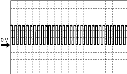
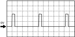
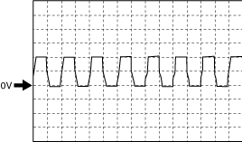
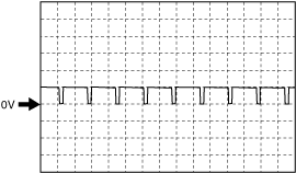
Inspection Using An Oscilloscope (Reference)
CMP (G+) signal
am6zzw00012043
|
Intake shutter valve (ISV-) signal
am6zzw00012044
|
EGR cooler bypass valve (-) (EGR-) signal
am6zzw00012044
|
Suction control valve signal
am6zzw00012046
|
am6zzw00012047
|
A/F sensor heater control signal
am6zzw00012048
|
Engine oil control signal
am6zzw00012652
|
Regulating valve actuator signal
am6zzw00012050
|
Fuel injection control (-) signal
am6zzw00012052
|
Fuel injection control (+) signal
am6zzw00012052
|
Generator output voltage signal
ac5wzw00012882
|
CKP (NE+) signal
ac5jjw00010634
|
Generator field coil control signal
am6zzw00012655
|
Using The M-MDS
1. Connect the M-MDS to the DLC-2.
2. Switch the ignition ON (engine off).
3. Measure the PID value.
PID/DATA monitor item table
|
Item (definition) |
Unit/Condition |
Definition |
Condition/Specification (Reference) |
|---|---|---|---|
|
AAT
|
°C, °F
|
Ambient air temperature
|
• Displays the ambient air temperature.
|
|
AC_PRES
|
KPa, Bar, psi
|
Refrigerant pressure
|
Idle
• A/C switch ON: Approx. 1.04 MPa {10.6 kgf/cm2, 151 psi}
|
|
AC_REQ
|
Off/On
|
A/C request signal
|
• A/C switch OFF: Off
• A/C switch ON: On
|
|
ACCS
|
Off/On
|
A/C relay
|
• A/C relay is OFF: Off
• A/C relay is ON: On
|
|
AIRSHUT_ACT
|
Displays in the Mazda Modular Diagnostic System (M-MDS) but it does not operate.
|
||
|
AIRSHUT_CAL
|
|||
|
ALTT V
|
V
|
Generator output voltage
|
• Switch the ignition ON (engine off): 0 V
• idle: Approx. 10.75 V
• Racing (engine speed 2,000 rpm): Approx. 10.75 V
|
|
AMB_TEMP
|
°C, °F
|
Ambient air temperature
|
• Displays the ambient air temperature.
|
|
APP
|
%
|
APP sensor No.1 voltage
|
• Accelerator pedal released: Approx. 0%
• Accelerator pedal depressed: Approx. 100%
|
|
APP1
|
V
|
APP sensor No.1 voltage
|
Switch the ignition ON (engine off)
• Accelerator pedal released: Approx. 0.78 V
• Accelerator pedal depressed: Approx. 4.52 V
|
|
%
|
APP sensor No.1
|
Switch the ignition ON (engine off)
• Accelerator pedal released: Approx. 0%
• Accelerator pedal depressed: Approx. 100%
|
|
|
APP2
|
V
|
APP sensor No.2 voltage
|
Switch the ignition ON (engine off)
• Accelerator pedal released: Approx. 0.39 V
• Accelerator pedal depressed: Approx. 2.26 V
|
|
%
|
APP sensor No.2
|
Switch the ignition ON (engine off)
• Accelerator pedal released: Approx. 0%
• Accelerator pedal depressed: Approx. 100%
|
|
|
ARPMDES
|
RPM
|
Target engine speed
|
• Displays the target engine speed.
|
|
AVE_DST_BW_DPF_RGN
|
km, ft, mi
|
Average distance between diesel particulate filter regens
|
• Displays the average distance between diesel particulate filter regens.
|
|
BARO
|
KPa, Bar, psi
|
Barometric pressure
|
• Displays the BARO.
|
|
BATT_CUR
|
A
|
Battery current
|
• Displays battery charge/discharge current value
|
|
BATT_DAY
|
—
|
Number of days elapsed since current sensor initialization
|
• Displays vehicle battery days in service
|
|
BATT_RES
|
—
|
Battery internal resistance (estimated)
|
• Displays battery inferred internal resistance
|
|
BATT_SOC
|
%
|
Battery charge condition (estimated)
|
• Displays battery estimated state of charge
|
|
BATT_TEMP
|
°C, °F
|
Battery temperature
|
• Displays battery fluid temperature
|
|
BATT_V
|
V
|
Battery voltage
|
• Displays battery voltage
|
|
BBP
|
KPa, Bar, psi
|
Power brake unit vacuum sensor
|
• Switch the ignition ON (engine off) and depress the brake pedal 10 times: Approx. 97.13 kPa {0.9904 kgf/cm2, 14.09 psi}
• idle: Approx. 7.6 kPa {0.077 kgf/cm2, 1.1 psi}
• The instant the brake pedal is depressed and released while idling: Approx. 47 kPa {0.48 kgf/cm2, 6.8 psi}
|
|
BFP
|
KPa, Bar, psi
|
Brake fluid pressure
|
Idle
• Brake pedal released: 0 kPa {0 kgf/cm2, 0 psi}
• Brake pedal depressed: Approx. 12 kPa {0.12 kgf/cm2, 1.7 psi}
|
|
BOO
|
High/Low
|
Brake switch (No.1 signal)
|
• Brake pedal released: Low
• Brake pedal depressed: High
|
|
BPA
|
High/Low
|
Brake switch (No.2 signal)
|
• Brake pedal released: Low
• Brake pedal depressed: High
|
|
BP_AC_ST_OPL
|
Displays in the Mazda Modular Diagnostic System (M-MDS) but it does not operate.
|
||
|
B20K_DST_TRV_IND
|
|||
|
B30K_DST_TRV_IND
|
|||
|
B40K_DST_TRV_IND
|
|||
|
C_B10K_DST_TRV
|
|||
|
C_B10K_DST_TRV_IND
|
|||
|
C_T_ACT_ACON
|
%
|
Commanded Intake shutter valve actuator
|
• Displays the boost air temperature.
|
|
CA_CT_B1S1
|
°C, °F
|
Boost air temperature
|
• Displays the boost air temperature.
|
|
CACT12
|
°C, °F
|
Boost air temperature
|
• Displays the boost air temperature.
|
|
CAP_SYS_10
|
Displays in the Mazda Modular Diagnostic System (M-MDS) but it does not operate.
|
||
|
CAP_SYS 13
|
|||
|
CAP_SYS 14
|
|||
|
CAP_SYS 15
|
|||
|
CAP_SYS 16
|
|||
|
CATT11_DSD
|
°C, °F
|
Catalytic converter temperature
|
• Displays estimated catalytic converter temperature
|
|
CC_DIFP_WOA
|
°C, °F
|
Actual difference in phase between camshaft and crankshaft (no correction)
|
• Displays the actual difference in phase between camshaft and crankshaft.
|
|
CCV_ACT
|
°(deg)
|
Actual coolant control valve opening angle
|
• Displays the actual coolant control valve opening angle
|
|
CCV_DSD
|
°(deg)
|
Target coolant control valve opening angle
|
• Displays the target coolant control valve opening angle
|
|
CKP_LC
|
Off/On
|
CKP sensor learning complete
|
• Displays the CKP sensor learning complete
|
|
CKP_LP
|
Off/On
|
CKP sensor learning preconditions
|
• Displays the CKP sensor learning preconditions
|
|
CL_NMHC_MN_CP
|
°(deg)
|
Catalyst monitoring completed/NMHC catalyst monitoring completed
|
• Displays the catalyst monitoring completed/NMHC catalyst monitoring completed.
|
|
CLR_DIST
|
—
|
Distance after DTC cleared
|
• Displays the mileage after DTC cleared.
|
|
CLU_CUT_SW
|
Off/On
|
Starter interlock switch
|
• Starter interlock switch ON: On
• Starter interlock switch OFF: Off
|
|
CLU_SW
|
Off/On
|
CPP switch
|
• Clutch pedal depressed: On
• Clutch pedal released: Off
|
|
CMP_MNT_ENA
|
Displays in the Mazda Modular Diagnostic System (M-MDS) but it does not operate.
|
||
|
COMP_BPV
|
Off/On
|
Compressor bypass valve
|
• Racing (engine speed above 3,000 rpm): ON
|
|
COMP3_MNT
|
—
|
Comprehensive component monitoring completed
|
• Displays the comprehensive component monitoring completed.
|
|
CP_IGN_SP
|
Displays in the Mazda Modular Diagnostic System (M-MDS) but it does not operate.
|
||
|
CPP*1
|
%
|
Clutch pedal position
|
• Displays the clutch pedal position
|
|
CPP/PNP*1
|
Off/On
|
Shift lever position
|
• Neutral: On
• Other than neutral: Off
|
|
CTLY_NMHC_MN
|
—
|
Catalyst monitoring / NMHC catalyst monitoring
|
• Displays the catalyst monitoring / NMHC catalyst monitoring.
|
|
CYLND_FEL_RATE
|
—
|
Cylinder fuel rate (mg/stroke)
|
• Displays the cylinder fuel rate.
|
|
DEF_CONC*2
|
%
|
AdBlue® concentration
|
• Displays the AdBlue® concentration.
|
|
DEF_T_TEMP*2
|
°C, °F
|
Urea tank temperature
|
• Displays the urea tank temperature.
|
|
DEF_TYPE*2
|
—
|
AdBlue® type
|
• Displays the AdBlue® type.
|
|
DNS_F_WF
|
km, ft, mi
|
Distance to next service for water in fuel
|
• Displays the distance to next service for water in fuel.
|
|
DPF_LMP
|
Off/On
|
Diesel particulate filter indicator light
|
• Diesel particulate filter indicator light not illuminate: Off
• Diesel particulate filter indicator light illuminate: On
|
|
DPF_LMP_CNT
|
—
|
Number of times diesel particulate filter indicator light illuminates
|
• Displays the number of times diesel particulate filter indicator light illuminates.
|
|
DPF_REG_CNT
|
—
|
Diesel particulate filter regeneration count
|
• Displays the diesel particulate filter regeneration count.
|
|
DPS_RGN_ST
|
—
|
Diesel particulate filter regen status
|
• Displays the diesel particulate filter regen status.
|
|
DV_RGT_CSPT_10K*2
|
Displays in the Mazda Modular Diagnostic System (M-MDS) but it does not operate.
|
||
|
DV_RGT_CSPT_20K*2
|
|||
|
DV_RGT_CSPT_30K*2
|
|||
|
DV_RGT_CSPT_40K*2
|
|||
|
DV_RGT_CSPT_ACT*2
|
|||
|
E_WP
|
|||
|
ECT
|
°C, °F
|
Engine coolant temperature
|
• Displays the ECT.
|
|
EG_FRC_PRS_TRQ
|
%
|
Engine friction-percent torque
|
• Displays the engine friction-percent torque.
|
|
EGR_C_BP
|
%
|
EGR cooler bypass valve
|
• Displays the EGR cooler bypass valve position.
|
|
EGR_C_BP_ACT
|
%
|
Actual measured EGR cooler bypass valve opening angle
|
ECT: above 70 °C {158 °F}
• idle: Approx. 0 % (after 20—30 s have elapsed since start the engine)
• Racing (engine speed 2,000 rpm): 0 %
|
|
EGR_LRN
|
V
|
EGR valve learning value (closed condition)
|
• Displays the EGR valve fully-closed learning value.
|
|
EGR_VVT_MN_CP
|
Displays in the Mazda Modular Diagnostic System (M-MDS) but it does not operate.
|
||
|
EGR_VVT_MNT
|
|||
|
EGRB_DC_POS
|
%
|
EGR valve actual duty cycle
|
• Displays the EGR valve actual duty cycle.
|
|
EGRP
|
%
|
EGR valve
|
• Displays the EGR valve position.
|
|
EGRP_ACT
|
%
|
EGR valve actual opening angle
|
ECT: above 70 °C {158 °F}
• idle: 0 % (after 20—30 s have elapsed since start the engine)
• Racing (engine speed 2,000 rpm): Approx. 60 %
|
|
EGRT
|
°C, °F
|
EGR gas temperature
|
• Displays the EGR gas temperature.
|
|
EGT_B1S5
|
°C, °F
|
Exhaust gas temperature (No.5)
|
• Displays the exhaust gas temperature.
|
|
EIAECD1_TT_TM1
|
Displays in the Mazda Modular Diagnostic System (M-MDS) but it does not operate.
|
||
|
EIAECD1_TT_TM2
|
|||
|
EIAECD10_TT_TM1
|
|||
|
EIAECD10_TT_TM2
|
|||
|
EIAECD2_TT_TM1
|
|||
|
EIAECD2_TT_TM2
|
|||
|
EIAECD3_TT_TM1
|
|||
|
EIAECD3_TT_TM2
|
|||
|
EIAECD4_TT_TM1
|
|||
|
EIAECD4_TT_TM2
|
|||
|
EIAECD5_TT_TM1
|
|||
|
EIAECD5_TT_TM2
|
|||
|
EIAECD6_TT_TM1
|
|||
|
EIAECD6_TT_TM2
|
|||
|
EIAECD7_TT_TM1
|
|||
|
EIAECD7_TT_TM2
|
|||
|
EIAECD8_TT_TM1
|
|||
|
EIAECD8_TT_TM2
|
|||
|
EIAECD9_TT_TM1
|
|||
|
EIAECD9_TT_TM2
|
|||
|
EN_CT1
|
|||
|
EN_CT2
|
|||
|
ENG_EXH_F_RATE
|
—
|
Engine exhaust flow rate(kg/h)
|
• Displays the engine exhaust flow rate.
|
|
ENG_FEL_RATE
|
g/s
|
Engine fuel rate
|
• Displays the engine fuel rate.
|
|
ENG_REF_TRQ
|
Nm
|
Engine reference torque
|
• Displays the engine reference torque.
|
|
EOL
|
mm
|
Engine oil level
|
• Displays the engine oil level
|
|
EOP
|
KPa, Bar, psi
|
Engine oil pressure
|
• Switch the ignition ON (engine off): Approx. −1 kPa {−0.01 kgf/cm2, −0.1 psi}
• idle: Approx. 184 kPa {1.88 kgf/cm2, 26.7 psi}
• Racing (engine speed 4,000 rpm): Approx. 366 kPa {3.73 kgf/cm2, 53.1 psi}
|
|
EOT
|
°C, °F
|
Engine oil temperature
|
• Displays the engine oil temperature.
|
|
EOT2
|
°C, °F
|
Engine oil temperature (Engine oil temperature from engine oil level sensor)
|
• Displays engine oil temperature.
|
|
ETC_DSD
|
Displays in the Mazda Modular Diagnostic System (M-MDS) but it does not operate.
|
||
|
EVAP_SYS_MN
|
Displays in the Mazda Modular Diagnostic System (M-MDS) but it does not operate.
|
||
|
EVAP_SYS_MN_CP
|
|||
|
EXHP_DIF_AVE
|
KPa, Bar, psi
|
Average value of the pressure difference before and after passing through the diesel particulate filter
|
• Displays average value of the pressure difference before and after passing through the diesel particulate filter.
|
|
EXHPRES1
|
KPa, Bar, psi
|
Exhaust gas pressure (No.1)
|
• idle: Approx. 100 kPa {1.02 kgf/cm2, 14.5 psi}
• Racing (engine speed above 4,000 rpm): Approx. 193 kPa {1.97 kgf/cm2, 28.0 psi}
• Racing (engine speed above 5,000 rpm): Approx. 266 kPa {2.71 kgf/cm2, 38.6 psi}
|
|
EXHPRESS_DIF
|
KPa, Bar, psi
|
Exhaust gas pressure (No.2)
|
• Displays the difference in pressure between exhaust gas pressure before and after passing the diesel particulate filter.
|
|
EXHSHUT_ACT
|
Displays in the Mazda Modular Diagnostic System (M-MDS) but it does not operate.
|
||
|
EXHSHUT_DSD
|
|||
|
EXHTEMP
|
°C, °F
|
Exhaust gas temperature (No.1)
|
• Displays the exhaust gas temperature.
|
|
EXHTEMP1
|
°C, °F
|
Exhaust gas temperature (No.2)
|
• Displays the exhaust gas temperature.
|
|
EXHTEMP2
|
°C, °F
|
Exhaust gas temperature (No.3)
|
• Displays the exhaust gas temperature.
|
|
EXHTEMP4*2
|
°C, °F
|
Exhaust gas temperature (No.4)
|
• Displays the exhaust gas temperature.
|
|
FAN_DUTY
|
%
|
Fan control module No.1
|
Idle
• ECT is below 100 °C {212 °F}: 0 %
• ECT is above 100 °C {212 °F}: Approx. 34 % (after a certain period has elapsed from when ECT reaches 100 °C {212 °F})
|
|
FAN_DUTY2
|
%
|
Fan control module No.2
|
Idle
• ECT is below 100 °C {212 °F}: 0 %
• ECT is above 100 °C {212 °F}: Approx. 34 % (after a certain period has elapsed from when ECT reaches 100 °C {212 °F})
|
|
FEL_IJCQ_CTL1ST
|
No/Yes
|
Fuel injection quantity control status
|
• Displays the fuel injection quantity control status.
|
|
FEL_IJCT_CTL1ST
|
No/Yes
|
Fuel injection timing control status
|
• Displays the fuel injection timing control status.
|
|
FEL_PRE_CTL1ST
|
No/Yes
|
Fuel pressure control status
|
• Displays the fuel pressure control status.
|
|
FF_CLG
|
No/Yes
|
Fuel Filter clogged
|
• Displays the fuel Filter clogged
|
|
FIA_DSD
|
—(mm3/Stroke)
|
Supply pump flow desired value
|
• Displays the supply pump flow desired value.
|
|
FIP_FL
|
A
|
Supply pump flow control current
|
• Switch the ignition ON (engine off): 0 A
• idle: Approx. 1.87 A
• Racing (engine speed above 4,000 rpm): Approx. 1.75 A
|
|
FIP_SCV
|
A
|
Suction control valve
|
• Switch the ignition ON (engine off): Approx. 44 mA
• idle: Approx. 1.91 A
• Racing (engine speed above 4,000 rpm): Approx. 1.79 A
|
|
FP_DUTY
|
%
|
Supply pump duty cycle
|
• Switch the ignition ON (engine off): 0 %
• idle: Approx. 50 %
• Racing (engine speed above 4,000 rpm): Approx. 46 %
|
|
FP_RCV
|
—(ms)
|
Fuel pressure relief valve operation time
|
• Switch the ignition ON (engine off): 0
• idle: 0
• Racing (engine speed above 4,000 rpm): 0
|
|
FQ_OIL
|
g/s
|
Fuel quantity in oil
|
• Displays the fuel quantity in oil.
|
|
FQ_OIL_T
|
g/s
|
Fuel quantity in oil total
|
• Displays the fuel quantity in oil total.
|
|
FRP
|
KPa, Bar, psi
|
Common rail pressure
|
• Switch the ignition ON (engine off): 0—130 kPa {0—1.32 kgf/cm2, 0—18.8 psi}
• idle: Approx. 40 MPa {408 kgf/cm2, 5802 psi}
• Racing (engine speed above 4,000 rpm): Approx. 80 MPa {816 kgf/cm2, 11603 psi}
|
|
FRP_A
|
KPa {MPa}, mBar {Bar}, psi, in H20
|
Common rail pressure
|
• Ignition switched ON (engine off): Approx. 0—130 MPa {0—1.32 kgf/cm2, 0—18.8 psi}
• Idle (after warm up): Approx. 40 MPa {408 kgf/cm2, 5802 psi}
• Racing (engine speed is 4,000 rpm): Approx. 80 MPa {816 kgf/cm2, 11603 psi}
|
|
FRP_A_CMD
|
KPa {MPa}, mBar {Bar}, psi, in H20
|
Common rail pressure desired value
|
• Displays the common rail pressure desired value.
|
|
FRT_A
|
°C, °F
|
Fuel temperature inside the fuel supply line
|
• Displays the fuel temperature inside the fuel supply line.
|
|
FU_SYS_CP
|
Displays in the Mazda Modular Diagnostic System (M-MDS) but it does not operate.
|
||
|
FU_SYS_ENA
|
|||
|
GENVDSD
|
V
|
Generator Voltage Desired
|
• Displays the generator voltage desired.
|
|
GLABL_CY1
|
Displays in the Mazda Modular Diagnostic System (M-MDS) but it does not operate.
|
||
|
GLABL_CY2
|
|||
|
GLABL_CY3
|
|||
|
GLABL_CY4
|
|||
|
GLENA_O11V
|
|||
|
GLENA_PREGL
|
|||
|
GLENA_RGN
|
|||
|
GLENA_RGNM
|
|||
|
GLENA_U11V
|
|||
|
GLLIFE_CY1
|
|||
|
GLLIFE_CY2
|
|||
|
GLLIFE_CY3
|
|||
|
GLLIFE_CY4
|
|||
|
GLOW_P_V
|
|||
|
GLRM_CY1
|
|||
|
GLRM_CY2
|
|||
|
GLRM_CY3
|
|||
|
GLRM_CY4
|
|||
|
GP_LMP
|
Off/On
|
Glow indicator light
|
• Glow indicator light not illuminated: Off
• Glow indicator light illuminated: On
|
|
GPC_DUTY
|
%
|
Glow plug coil duty cycle
|
• Switch the ignition ON (engine off): 0 %
Idle
• ECT is 36 °C {86 °F}: Approx. 51 %
• After a certain period has elapsed from when ECT exceeds 40 °C {104 °F}: 0 %
|
|
GPL_OP_ST
|
Displays in the Mazda Modular Diagnostic System (M-MDS) but it does not operate.
|
||
|
GPL_ST_SUP
|
|||
|
HT_NOX_SRC_MN
|
|||
|
HTR11
|
%
|
A/F sensor heater control
|
• Switch the ignition ON (engine off): 0 %
• idle: Approx. 10.49 %
• Racing (engine speed above 4,000 rpm): Approx. 50 %
|
|
IAT_B1S1
|
°C, °F
|
Intake air temperature (No.1)
|
• Displays the intake air temperature (No.1).
|
|
IAT_B1S2
|
°C, °F
|
Intake air temperature (No.2)
|
• Displays the intake air temperature (No.2).
|
|
IAT13
|
Displays in the Mazda Modular Diagnostic System (M-MDS) but it does not operate.
|
||
|
ICP1
|
KPa {MPa}, mBar {Bar}, psi, in H20
|
Fuel pressure sensor (built into fuel injector No.1)
|
• Displays the fuel pressure sensor (built into fuel injector No.1).
|
|
ICP2
|
KPa {MPa}, mBar {Bar}, psi, in H20
|
Fuel pressure sensor (built into fuel injector No.2)
|
• Displays the fuel pressure sensor (built into fuel injector No.2).
|
|
ICP3
|
KPa {MPa}, mBar {Bar}, psi, in H20
|
Fuel pressure sensor (built into fuel injector No.3)
|
• Displays the fuel pressure sensor (built into fuel injector No.3).
|
|
ICP4
|
KPa {MPa}, mBar {Bar}, psi, in H20
|
Fuel pressure sensor (built into fuel injector No.4)
|
• Displays the fuel pressure sensor (built into fuel injector No.4).
|
|
IDC_SYS_ACT
|
Displays in the Mazda Modular Diagnostic System (M-MDS) but it does not operate.
|
||
|
IFT1
|
KPa {MPa}, mBar {Bar}, psi, in H20
|
Fuel temperature sensor (built into fuel injector No.1)
|
• Displays the fuel temperature sensor (built into fuel injector No.1).
|
|
IFT2
|
KPa {MPa}, mBar {Bar}, psi, in H20
|
Fuel temperature sensor (built into fuel injector No.2)
|
• Displays the fuel temperature sensor (built into fuel injector No.2).
|
|
IFT3
|
KPa {MPa}, mBar {Bar}, psi, in H20
|
Fuel temperature sensor (built into fuel injector No.3)
|
• Displays the fuel temperature sensor (built into fuel injector No.3).
|
|
IFT4
|
KPa {MPa}, mBar {Bar}, psi, in H20
|
Fuel temperature sensor (built into fuel injector No.4)
|
• Displays the fuel temperature sensor (built into fuel injector No.4).
|
|
INCR_RGT_10K
|
Displays in the Mazda Modular Diagnostic System (M-MDS) but it does not operate.
|
||
|
INCR_RGT_20K
|
|||
|
INCR_RGT_30K
|
|||
|
INCR_RGT_40K
|
|||
|
INCR_RGT_ACT
|
|||
|
INGEAR*3
|
Off/On
|
Gears are engaged
|
• Selector lever at R, D or M position: ON
• Selector lever at P or N position: OFF
|
|
INJ1_CMP
|
—(mm3/Stroke)
|
Fuel injector No.1 correction value
|
• Switch the ignition ON (engine off): Approx. −0.2
• idle: Approx. −0.03
• Racing (engine speed above 4,000 rpm): 0
|
|
INJ2_CMP
|
—(mm3/Stroke)
|
Fuel injector No.2 correction value
|
• Switch the ignition ON (engine off): Approx. 0.27
• idle: Approx. −0.06
• Racing (engine speed above 4,000 rpm): 0
|
|
INJ3_CMP
|
—(mm3/Stroke)
|
Fuel injector No.3 correction value
|
• Switch the ignition ON (engine off): Approx. 0.01
• idle: Approx. 0.03
• Racing (engine speed above 4,000 rpm): 0
|
|
INJ4_CMP
|
—(mm3/Stroke)
|
Fuel injector No.4 correction value
|
• Switch the ignition ON (engine off): Approx. −0.01
• idle: Approx. 0.03
• Racing (engine speed above 4,000 rpm): 0
|
|
INLET_PRES
|
V
|
Manifold absolute pressure (No.1)
|
• Displays the manifold absolute pressure (No.1).
|
|
INTK_MAPA
|
KPa, Bar, psi
|
Manifold absolute pressure (No.2)
|
• Displays the manifold absolute pressure (No.2).
|
|
ISC_FBK
|
%
|
ISC feedback value
|
• Displays ISC feedback value
|
|
ISC_FBK_LRN
|
%
|
Learning value for calculating ISC feedback amount
|
• Displays learning value for calculating ISC feedback amount
|
|
I-Stop_OFF
|
Displays in the Mazda Modular Diagnostic System (M-MDS) but it does not operate.
|
||
|
I-Stop_TRD
|
|||
|
I-Stop_VSP
|
|||
|
I-Stop_VST
|
|||
|
ISV_ACT
|
°(deg)
|
Intake shutter valve control actual value
|
• Switch the ignition ON (engine off): Approx. 88.28
• idle: Approx. 4.36
• Racing (engine speed above 4,000 rpm): Approx. 82.5
|
|
ISV_DSD
|
°(deg)
|
Intake shutter valve control desired value
|
• Displays the intake shutter valve control desired value.
|
|
%
|
|||
|
ISV_LRN_C
|
°(deg)
|
Intake shutter valve learning value (closed)
|
• Displays the intake shutter valve learning value (closed).
|
|
ISV_POS
|
%
|
Intake shutter valve
|
• Switch the ignition ON (engine off): Approx. 88.23 %
• idle: Approx. 4.31 %
• Racing (engine speed above 4,000 rpm): Approx. 82.35 %
|
|
LN_IT_NCMP1
|
—
|
Fuel injector injection amount learning: not completed 1
|
• Displays the fuel injector injection amount learning is not completed 1.
|
|
LN_IT_NCMP2
|
—
|
Fuel injector injection amount learning: not completed 2
|
• Displays the fuel injector injection amount learning is not completed 2.
|
|
LOAD
|
%
|
Engine load
|
• idle: Approx. 2.35 %
• Racing (engine speed above 4,000 rpm): Approx. 2.35 %
• Racing (engine speed above 5,000 rpm): Approx. 80 % or more
|
|
LP_EGR_ACT
|
Displays in the Mazda Modular Diagnostic System (M-MDS) but it does not operate.
|
||
|
LPEGR_DSD
|
|||
|
M_GEAR
|
|||
|
MAF
|
g/Sec
|
Mass air flow
|
• Switch the ignition ON (engine off): Approx. 1.00 g/s {0.132 lb/min}
• idle: Approx. 5.47 g/s {0.724 lb/min}
• Racing (engine speed 2,000 rpm): Approx. 13.84 g/s {1.831 lb/min}
• Racing (engine speed 4,000 rpm): Approx. 85.13 g/s {11.26 lb/min}
|
|
MAP_DSD
|
KPa, Bar, psi
|
Manifold absolute pressure (No.2) desired value
|
• Displays the manifold absolute pressure (No.2) desired value.
|
|
MAX_SEN_VAL17
|
Displays in the Mazda Modular Diagnostic System (M-MDS) but it does not operate.
|
||
|
MAX_SEN_VAL18
|
|||
|
MAX_SEN_VAL19
|
|||
|
MAX_SEN_VAL20
|
|||
|
MIL
|
Off/On
|
Check engine light
|
• Check engine light not illuminate: Off
• Check engine light illuminate: ON
|
|
MIL_DIS
|
km, ft, mi
|
Travelled distance since check engine light illuminated
|
• Displays the travelled distance since check engine light illuminated.
|
|
MIN_ACT_MIL
|
—
|
Minutes run by the engine while check engine light activated (min)
|
• Displays the minutes run by the engine while check engine light activated.
|
|
MIN_SEN_VAL17
|
Displays in the Mazda Modular Diagnostic System (M-MDS) but it does not operate.
|
||
|
MIN_SEN_VAL18
|
|||
|
MN_SEN_VAL19
|
|||
|
MIN_SEN_VAL20
|
|||
|
MSF_CP
|
|||
|
MSF_ENA
|
|||
|
NEUTRAL_SW1
|
|||
|
NEUTRAL_SW2
|
|||
|
NOX_ADS_DSFR_ST
|
|||
|
NOX_ADS_RGN_ST
|
|||
|
NOX_C_B1S1*2
|
— (ppm)
|
The exhaust gas NOx concentration before SCR converter
|
• Displays the exhaust gas NOx concentration before SCR converter.
|
|
NOX_EMI_T_HI_10K*2
|
Displays in the Mazda Modular Diagnostic System (M-MDS) but it does not operate.
|
||
|
NOX_EMI_T_HI_20K*2
|
|||
|
NOX_EMI_T_HI_30K*2
|
|||
|
NOX_EMI_T_HI_40K*2
|
|||
|
NOX_EMI_T_HI_ACT*2
|
|||
|
NOX_SRC_MN_CP*2
|
|||
|
NOX_SCC_B1S1*2
|
— (ppm)
|
NOx sensor No.1 corrected concentration
|
• Displays the NOx sensor No.1 corrected concentration.
|
|
O2
|
%
|
Oxygen concentration in exhaust gas
|
• Switch the ignition ON (engine off): 0 %
• idle: 13.9 %
• Racing (engine speed above 4,000 rpm): Approx. 16.8 %
• Deceleration fuel cut: Approx. 22 %
|
|
O2_SEN_CCT_B1S1
|
%
|
Oxygen concentratio
|
• Displays the Oxygen concentration.
|
|
O2_SEN_CCT_B1S2
|
%
|
Oxygen concentratio
|
• Displays the Oxygen concentration.
|
|
O2_SEN_CCT_B1S3
|
%
|
Oxygen concentratio
|
• Displays the Oxygen concentration.
|
|
O2_SEN_LMD_B1S1
|
%
|
Oxygen lambda
|
• Displays the Oxygen concentration.
|
|
O2_SEN_LMD_B1S2
|
%
|
Oxygen lambda
|
• Displays the Oxygen concentration.
|
|
O2_SEN_LMD_B1S3
|
%
|
Oxygen lambda
|
• Displays the Oxygen concentration.
|
|
O2_SH_PM_F
|
No/Yes
|
Oxygen sensor heater monitoring / PM filter monitoring
|
• Displays oxygen sensor heater monitoring / PM filter monitoring
|
|
O2_SH_PM_F_CP
|
No/Yes
|
Oxygen sensor heater monitoring completed / PM filter monitoring completed
|
• Displays oxygen sensor heater monitoring completed / PM filter monitoring completed
|
|
O2_SM_EGSM
|
No/Yes
|
Oxygen sensor monitoring / Exhaust gas sensor monitoring
|
• Displays oxygen sensor monitoring / Exhaust gas sensor monitoring
|
|
O2_SM_EGSM_CP
|
No/Yes
|
Oxygen sensor monitoring completed / Exhaust gas sensor monitoring completed
|
• Displays oxygen sensor monitoring completed / Exhaust gas sensor monitoring completed
|
|
O2S_IMP
|
Ω
|
A/F sensor element impedance
|
• Displays the A/F sensor element impedance.
|
|
O2S11
|
µA
|
A/F sensor current
|
• idle: Approx. 1.01 mA
• Deceleration fuel cut: Approx. 3.84 mA
|
|
V
|
A/F sensor voltage
|
• Switch ignition ON (engine off): 3.24 V
• Deceleration fuel cut: Approx. 3.74 V
|
|
|
O2S11_CAL
|
—
|
A/F sensor calibration value
|
• Switch the ignition ON (engine off): Approx. 1.09
• idle: Approx. 1.09
• Racing (engine speed above 4,000 rpm): Approx. 1.09
• Deceleration fuel cut: Approx. 1.09
|
|
O2S11_MODE
|
—
|
A/F sensor activation status
|
• Switch the ignition ON (engine off): 0
• idle: 0
• Racing (engine speed above 4,000 rpm): 3
• Deceleration fuel cut: 3
|
|
OIL_DIL
|
kg, lb
|
Engine oil dilution amount
|
• Displays the engine oil dilution amount.
|
|
OIL_P_DUTY
|
%
|
Engine oil pressure control circuit duty cycle
|
• Switch the ignition ON (engine off): 0 %
• idle: Approx. 55 %
• Racing (engine speed above 4,000 rpm): 0 %
|
|
OILCHG_DIS
|
km, ft, mi
|
Distance from the last engine oil change
|
• Displays the distance from the last engine oil change.
|
|
PCVHC
|
%
|
Blow-by heater control
|
ECT: above 90 °C {194 °F}
• Switch the ignition ON (engine off): 0 %
• idle: 0 %
|
|
PM_ACC
|
—(g/l, lb/ft3)
|
PM accumulation amount
|
• Displays the PM accumulation amount.
|
|
PM_ACC_DSD
|
—(g/l, lb/ft3)
|
PM accumulation amount desired
|
• Displays the PM accumulation amount desired.
|
|
PM_GEN
|
—(g/l, lb/ft3)
|
PM generation amount
|
• Displays the PM generation amount.
|
|
PN_SW
|
Open/Closed
|
Park/Neutral position determination
|
• Selector lever at R, D or M position: Open
• Selector lever at P or N position: Closed
|
|
PRE_CHG_DIS
|
Displays in the Mazda Modular Diagnostic System (M-MDS) but it does not operate.
|
||
|
PRS_TRQ_ACT
|
%
|
Actual engine-percent torque
|
• Displays the actual engine-percent torque
|
|
PRS_TRQ_DEM
|
%
|
Driver's demand engine-percent torque
|
• Displays the driver's demand engine-percent torque
|
|
RE_LIFE
|
%
|
Remaining life
|
• Displays the remaining life
|
|
RE_MILA
|
km, ft, mi
|
Remaining milage
|
• Displays the remaining milage
|
|
REG_DIS
|
km, ft, mi
|
Distance since last diesel particulate filter regeneration
|
• Displays the distance since last diesel particulate filter regeneration.
|
|
REGVP
|
mm
|
Regulating valve actuator position sensor
|
• idle: Approx. 19.02 mm
• Racing (engine speed approx 3,500 rpm): Approx. 12.15 mm
|
|
REGVP_DSD
|
mm
|
Regulating valve actuator position desired value
|
• Displays the Regulating valve actuator position desired value
|
|
REL_THR_APOS
|
%
|
Relative throttle A position
|
• Displays the relative throttle A position
|
|
REV_SW
|
Off/On
|
Reverse position determination
|
• Displays the reverse position.
|
|
RGT_LV_T_LO_10K*2
|
Displays in the Mazda Modular Diagnostic System (M-MDS) but it does not operate.
|
||
|
RGT_LV_T_LO_20K*2
|
|||
|
RGT_LV_T_LO_30K*2
|
|||
|
RGT_LV_T_LO_40K*2
|
|||
|
RGT_LV_T_LO_ACT*2
|
|||
|
RLF_DIST
|
%
|
Remaining life (distance)
|
• Displays the remaining life (distance)
|
|
RLF_NTL
|
%
|
Remaining life (nitration)
|
• Displays the remaining life (nitration)
|
|
RLF_PERIOD
|
%
|
Remaining life (period)
|
• Displays the remaining life (period)
|
|
RLF_RESOT
|
%
|
Remaining life (remaining soot)
|
• Displays the remaining life (remaining soot)
|
|
RLF_TBNUM
|
%
|
Remaining life (total base number)
|
• Displays the remaining life (total base number)
|
|
RPM
|
RPM
|
Engine speed
|
• Displays the engine speed.
|
|
SDARS_BSPR_CP
|
Displays in the Mazda Modular Diagnostic System (M-MDS) but it does not operate.
|
||
|
SDARS_BSTPRE
|
|||
|
SED_SW
|
Off/On
|
Sedimentor switch
|
• There is no water in sedimentor: Off
• There is water in sedimentor: On
|
|
T_ENG_RT
|
hh:mm:ss
|
Total engine run time
|
• Displays the total engine run time
|
|
TB_LRN_FRQ
|
—
|
Frequency of completed turbocharger learning
|
• Displays the frequency of completed turbocharger learning.
|
|
TB_LRN_FRQ
|
—
|
Frequency of completed turbocharger learning
|
• Displays frequency of completed turbocharger learning
|
|
TCA_CINP
|
KPa, Bar, psi
|
Manifold absolute pressure (No.1)
|
• idle: Approx. 104 kPa {1.06 kgf/cm2, 15.1 psi}
• Racing (engine speed above 4,000 rpm): Approx. 152 kPa {1.54 kgf/cm2, 22.0 psi}
• Racing (engine speed above 5,000 rpm): Approx. 176 kPa {1.79 kgf/cm2, 25.5 psi}
|
|
TFIQ_AFL_SM
|
— (mm3/stroke)
|
Target fuel injection quantity after limitation for smoke
|
• Displays the target fuel injection quantity after limitation for smoke
|
|
TIM_CLR_DTC
|
—
|
Time since DTCs cleared (min)
|
• Displays time since DTCs cleared (min)
|
|
TIRT
|
hh:mm:ss
|
Total idle run time
|
• Displays total idle run time
|
|
TIRT_SUP
|
—
|
Total idle run time supported
|
• Displays total idle run time supported
|
|
TRT_PTO_ACT_SUP
|
—
|
Total run time with PTO active supported
|
• Displays total run time with PTO active supported
|
|
VEH_FEL_RATE
|
g/sec
|
Vehicle fuel rate
|
• Displays the vehicle fuel rate
|
|
VGT_CMODE
|
—
|
Turbocharger Control Mode
|
• Displays total run time with PTO active supported
|
|
VGTURB_ACT
|
Displays in the Mazda Modular Diagnostic System (M-MDS) but it does not operate.
|
||
|
VGTURB_DSD
|
|||
|
VPWR
|
V
|
Battery positive voltage
|
• Switch the ignition ON (engine off): Approx. 12.78 V
• idle: Approx. 13.78 V
|
|
VSS
|
KPH, MPH
|
Vehicle speed
|
• Displays the vehicle speed.
|
|
WGV
|
Displays in the Mazda Modular Diagnostic System (M-MDS) but it does not operate.
|
||
|
WT_LEV_CNT
|
—
|
Number of times sedimentor switch operates
|
• Displays the number of times sedimentor switch operates.
|