49 G027 006
Installer

49 H027 002
Bearing remover

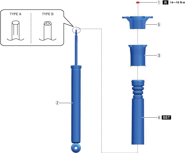
REAR SHOCK ABSORBER DISASSEMBLY/ASSEMBLY
id021400900000
Special service tool (SST)
|
49 G027 006
Installer
|
|
49 H027 002
Bearing remover
|
|
Replacement part
|
Piston rod nut
Quantity: 1
Location of use: Rear shock absorber
|
Oil and Chemical Type
|
Rubber grease
Type: NIPPON GREASE RUBBER GREASE
|
1. Remove the rear shock absorber. (See REAR SHOCK ABSORBER REMOVAL/INSTALLATION.)
2. Remove in the order indicated in the table.
3. Install in the reverse order of removal.
am6zzw00018603
|
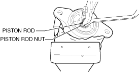
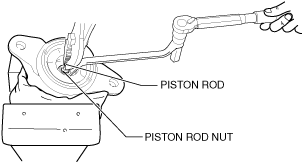
Piston Rod Nut Removal Note
Type A
1. Remove the piston rod nut using an offset box-end wrench and pliers.
ac5uuw00011062
|
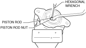
Type B
1. Remove the piston rod nut using an offset box-end wrench and a hexagonal wrench.
am6zzw00018599
|
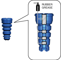
Bump Stopper, Mounting Rubber Assembly Note
1. Wipe off grease on the bump stopper component using a cloth.
2. Apply rubber grease to the inside of the bump stopper component.
ac5uuw00011063
|
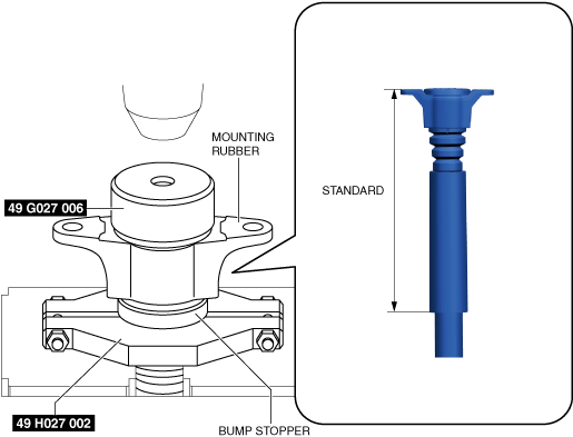
3. Assemble the bump stopper component and the mounting rubber using the SSTs and a press.
ac5uuw00011219
|
4. Verify that the assembly position of the bump stopper and the mounting rubber is within the standard.
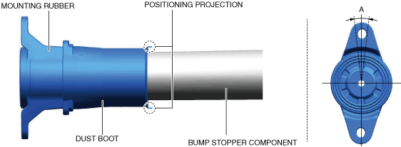
Dust Boot Installation Note
1. Assemble the dust boot to position A shown in the figure.
ac5uuw00011220
|
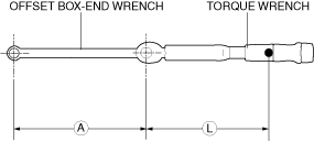
Piston Rod Nut Installation Note
1. Install the offset box-end wrench to the torque wrench as shown in the figure, set it on the piston rod nut, and measure dimensions A and L shown in the figure.
ac5wzw00014326
|
2. Tighten the piston rod nut after calculating the tightening torque using the following formula.
Type A
ac5wzw00014327
|
Type B
am6xuw00013311
|