 |
am6xuw00011536
WHEEL HUB COMPONENT REMOVAL/INSTALLATION [4WD]
id0312008004a2
1. Switch the ignition ON (engine off).
2. Release the electric parking brake.
3. Switch the ignition off.
4. Disconnect the negative battery terminal. (See NEGATIVE BATTERY TERMINAL DISCONNECTION/CONNECTION.)
5. Remove the wheel and tire. (See WHEEL AND TIRE REMOVAL/INSTALLATION.)
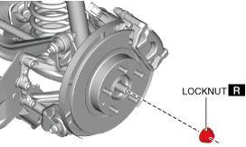
6. Remove the locknut with the brake pedal depressed. (See Locknut Installation Note.)
am6xuw00011536
|
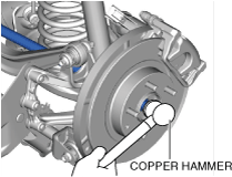
7. Install a spare nut onto the drive shaft.
8. Tap the nut with a copper hammer and separate the drive shaft from the axle.
am6xuw00011537
|
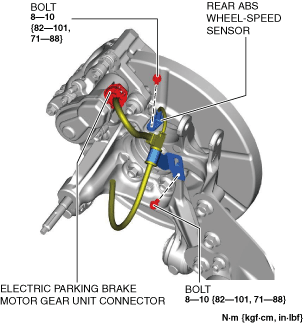
9. Disconnect the rear ABS wheel-speed sensor wiring harness and the electric parking brake motor gear unit connector and set it aside so that it does not interfere with the servicing.
am6xuw00011538
|
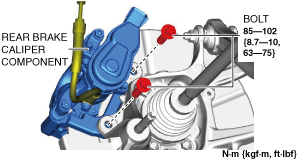
10. Remove the front brake caliper component installation bolts.
am6xuw00011539
|
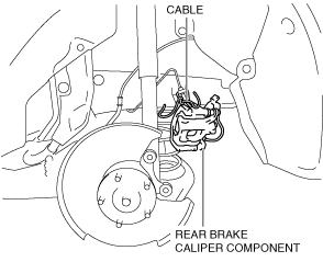
11. Remove the rear brake caliper component and suspend it out of the way using a cable.
ac9uuw00008034
|
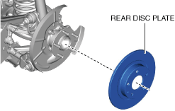
12. Remove the rear disc plate.
am6xuw00011540
|
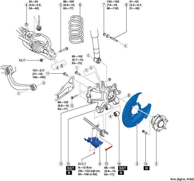
13. Remove in the order indicated in the table.
14. Install in the reverse order of removal. (See Suspension Links Installation Note.)
15. When the hub support, hub support bushing (front), or hub support bushing (rear) is replaced, inspect the wheel alignment and adjust it if necessary. (See REAR WHEEL ALIGNMENT.)
am6xuw00011541
|
|
1
|
Bolt (wheel hub)
|
|
2
|
Wheel hub
|
|
3
|
Dust cover
|
|
4
|
Rear stabilizer control link lower side nut
|
|
5
|
Rear lower arm outer bolt
|
|
6
|
Rear coil spring
|
|
7
|
Rear shock absorber lower nut
|
|
8
|
Stud bolt
|
|
9
|
Protector
|
|
10
|
Rear lateral link outer bolt
|
|
11
|
Rear trailing link installation bolt
|
|
12
|
Bolt (rear upper arm outer side)
|
|
13
|
Hub support
|
|
14
|
Wheel hub bolt
(See Wheel Hub Bolt Removal Note.)
|
|
15
|
Hub support bushing (front)
|
|
16
|
Hub support bushing (rear)
|
Rear Lower Arm Outer Bolt Removal Note
1. Support the rear lower arm using a jack.
ac5uuw00008483
|
2. Remove the rear lower arm outer bolt.
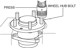
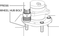
Wheel Hub Bolt Removal Note
1. Remove the wheel hub bolt using a press.
am6xuw00011542
|
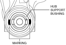
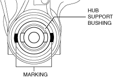
Hub Support Bushing (Front) Removal Note
1. Mark the hub support as shown in the figure.
am6xuw00011543
|
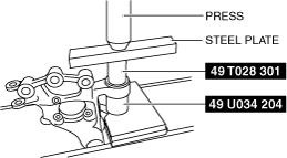
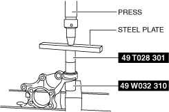
2. Press the rear hub support bushing (front) out using the SSTs.
am6xuw00011544
|
Hub Support Bushing (Rear) Removal Note
1. Mark the hub support as shown in the figure.
am6xuw00011545
|
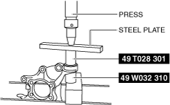
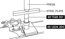
2. Press the rear hub support bushing (rear) out using the SSTs.
am6xuw00011546
|
Suspension Links Installation Note
1. When installing the joint sections with rubber bushings, perform the following procedures.
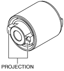
Hub Support Bushing (Rear) Installation Note
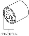
1. Align the projection of the bushing with the hub support marking and set a new bushing to the hub support.
ac5wzw00002568
|
2. Install a new hub support bushing (rear) using the SSTs.
am6xuw00011547
|
Hub Support Bushing (Front) Installation Note
1. Align the projection of the bushing with the hub support marking and set a new bushing to the hub support.
ac5wzw00002570
|
2. Install a new hub support bushing (front) using the SSTs.
am6xuw00011548
|
Wheel Hub Bolt Installation Note
1. Install the new wheel hub bolt using a press.
am6xuw00011549
|
Locknut Installation Note
1. If dust or grease is on the drive shaft thread area, wipe it off with a cloth.
2. Tighten the locknut using the following procedure and with the brake pedal depressed.