|
am6xuw00011646
REAR DIFFERENTIAL ASSEMBLY
id031400146600
1. Assemble in the order indicated in the table.
am6xuw00011646
|
|
1
|
Gear case
|
|
2
|
Side bearing
(See Side Bearing Assembly Note.)
|
|
3
|
Thrust washer
(See Thrust washer Assembly Note.)
|
|
4
|
Side gear
|
|
5
|
Thrust washer
|
|
6
|
Pinion gear
|
|
7
|
Pinion shaft
|
|
8
|
Pin
|
|
9
|
Ring gear
(See Ring Gear Assembly Note.)
|
|
10
|
Differential carrier
|
|
11
|
Bearing outer race
|
|
12
|
Spacer
|
|
13
|
Bearing inner race (rear bearing)
|
|
14
|
Bearing inner race (front bearing)
|
|
15
|
Collapsible spacer
|
|
16
|
Drive pinion
|
|
17
|
Locknut
(See Locknut Assembly Note.)
|
|
18
|
Adjusting shim (LH)
(See Adjusting Shim Assembly Note.)
|
|
19
|
Spacer
|
|
20
|
Rear differential component
|
|
21
|
Adjusting shim (RH)
(See Adjusting Shim Assembly Note.)
|
|
22
|
Rear cover
(See Rear Cover Assembly Note.)
|
|
23
|
Differential oil temperature sensor
|
|
24
|
Oil seal (Side gear)
|
|
25
|
Oil seal (Coupling component)
|
Side Bearing Assembly Note
1. Press the side bearing inner races into the gear case using the SSTs.
ac5jjw00010900
|
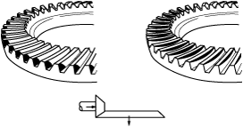
Thrust washer Assembly Note
1. Assemble the side gears, thrust washers and pinion gears to the gear case, then assemble the knock pin.
2. After assembling the knock pin, make a crimp so that the pin will not come out of the gear case.
3. Set a dial gauge to the pinion gear as indicated in the figure.
am6xuw00011647
|
4. Secure one of the side gears.
5. Move the pinion gear and measure the backlash at the end of the pinion gear.
Thrust washer thickness
|
Identification mark |
Thickness |
|---|---|
|
9
|
0.90 mm {0.035 in}
|
|
95
|
0.95 mm {0.037 in}
|
|
0
|
1.00 mm {0.0394 in}
|
|
05
|
1.05 mm {0.0413 in}
|
|
1
|
1.10 mm {0.0433 in}
|
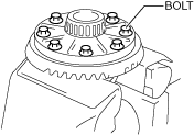
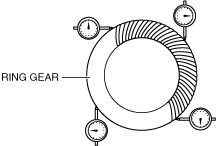
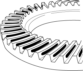
Ring Gear Assembly Note
1. Align the marks placed on the ring gear case at the time of disassembly and tighten the bolts in diagonal order.
am6xuw00011648
|
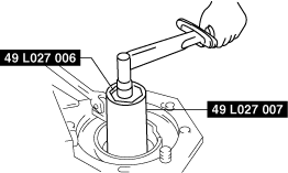
Bearing Outer Race Assembly Note
1. Press in the bearing outer race using the SSTs and a press.
am6xuw00011649
|
Spacer, Bearing Inner Race Assembly Note
1. Install a new spacer of the same size as the originally installed spacer.
Spacer thickness
|
Identification mark |
Thickness (mm {in}) |
Identification mark |
Thickness (mm {in}) |
|---|---|---|---|
|
08
|
3.08 {0.1213}
|
29
|
3.29 {0.1295}
|
|
09
|
3.095 {0.1219}
|
30
|
3.305 {0.1301}
|
|
11
|
3.11 {0.1224}
|
32
|
3.32 {0.1307}
|
|
12
|
3.125 {0.1230}
|
33
|
3.335 {0.1313}
|
|
14
|
3.14 {0.1236}
|
35
|
3.35 {0.1319}
|
|
15
|
3.155 {0.1242}
|
36
|
3.365 {0.1325}
|
|
17
|
3.17 {0.1248}
|
38
|
3.38 {0.1331}
|
|
18
|
3.185 {0.1254}
|
39
|
3.395 {0.1337}
|
|
20
|
3.20 {0.1260}
|
41
|
3.41 {0.1343}
|
|
21
|
3.215 {0.1266}
|
42
|
3.425 {0.1348}
|
|
23
|
3.23 {0.1272}
|
44
|
3.44 {0.1354}
|
|
24
|
3.245 {0.1278}
|
45
|
3.455 {0.1360}
|
|
26
|
3.26 {0.1283}
|
47
|
3.47 {0.1366}
|
|
27
|
3.275 {0.1289}
|
—
|
—
|
2. Press the bearing inner race (rear bearing) into the drive pinion using the SSTs and a press.
am6xuw00011650
|
Locknut Assembly Note
Drive pinion preload adjustment
1. Apply differential oil to a new locknut.
2. Assemble a new collapsible spacer, bearing inner race (front bearing), spacer and locknut to the drive pinion, and temporarily tighten the locknut.
3. Turn the serrated part of the drive pinion by hand to seat the bearing.
4. Tighten the locknut temporarily tightened in Step 1 from the lower limit of the specified tightening torque using the SSTs, and make this the specified preload.
aaxjjw00008286
|
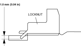
5. Crimp the locknut using a chisel and hammer.
acxuuw00003157
|
Adjusting Shim Assembly Note
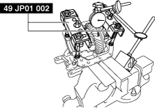
1. Assemble the differential carrier to the SSTs.
2. Assemble the spacer to the differential carrier.
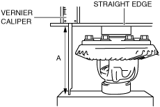
3. Using a vernier caliper and straight edge, measure the height of the rear differential component. This is dimension A.
am6xuw00011651
|
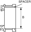
4. Measure the width of the installed differential in the differential carrier with the spacer installed. This is value B.
acxuuw00003159
|
5. The combined thickness of the left and right adjusting shims is obtained by the following formula.
C1= B – A + 0.115 mm {0.00453 in}
6. If the combined thickness of the previously installed adjusting shims is between C1 and C2, use the shims as they are.
7. If the combined thickness of the previously installed adjusting shims is not between C1 and C2, or if the adjusting shims have to be replaced, select two appropriate adjusting shims from the table below.
Adjusting shim thickness
|
Identification mark |
Thickness (mm {in}) |
Identification mark |
Thickness (mm {in}) |
|---|---|---|---|
|
339
|
3.39 {0.133}
|
393
|
3.93 {0.155}
|
|
342
|
3.42 {0.135}
|
396
|
3.96 {0.156}
|
|
345
|
3.45 {0.136}
|
399
|
3.99 {0.157}
|
|
348
|
3.48 {0.13}
|
402
|
4.02 {0.158}
|
|
351
|
3.51 {0.138}
|
405
|
4.05 {0.159}
|
|
354
|
3.54 {0.139}
|
408
|
4.08 {0.161}
|
|
357
|
3.57 {0.141}
|
411
|
4.11 {0.162}
|
|
360
|
3.60 {0.142}
|
414
|
4.14 {0.163}
|
|
363
|
3.63 {0.143}
|
417
|
4.17 {0.164}
|
|
366
|
3.66 {0.144}
|
420
|
4.20 {0.165}
|
|
369
|
3.69 {0.145}
|
423
|
4.23 {0.167}
|
|
372
|
3.72 {0.146}
|
426
|
4.26 {0.168}
|
|
375
|
3.75 {0.148}
|
429
|
4.29 {0.169}
|
|
378
|
3.78 {0.149}
|
432
|
4.32 {0.170}
|
|
381
|
3.81 {0.150}
|
435
|
4.35 {0.171}
|
|
384
|
3.84 {0.151}
|
438
|
4.38 {0.172}
|
|
387
|
3.87 {0.152}
|
441
|
4.41 {0.174}
|
|
390
|
3.90 {0.154}
|
—
|
—
|
8. Assemble the rear differential component to the differential carrier.
9. Tap the selected adjusting shim between the spacer and the bearing race with a plastic hammer.
10. Perform the ring gear and drive pinion backlash adjustment.
ac5jjw00010902
|
ac5jjw00010903
|
am6xuw00011652
|
Adjusting shim thickness
|
Identification mark |
Thickness (mm {in}) |
Identification mark |
Thickness (mm {in}) |
|---|---|---|---|
|
339
|
3.39 {0.133}
|
393
|
3.93 {0.155}
|
|
342
|
3.42 {0.135}
|
396
|
3.96 {0.156}
|
|
345
|
3.45 {0.136}
|
399
|
3.99 {0.157}
|
|
348
|
3.48 {0.137}
|
402
|
4.02 {0.158}
|
|
351
|
3.51 {0.138}
|
405
|
4.05 {0.159}
|
|
354
|
3.54 {0.139}
|
408
|
4.08 {0.161}
|
|
357
|
3.57 {0.141}
|
411
|
4.11 {0.162}
|
|
360
|
3.60 {0.142}
|
414
|
4.14 {0.163}
|
|
363
|
3.63 {0.143}
|
417
|
4.17 {0.164}
|
|
366
|
3.66 {0.144}
|
420
|
4.20 {0.165}
|
|
369
|
3.69 {0.145}
|
423
|
4.23 {0.167}
|
|
372
|
3.72 {0.146}
|
426
|
4.26 {0.168}
|
|
375
|
3.75 {0.148}
|
429
|
4.29 {0.169}
|
|
378
|
3.78 {0.149}
|
432
|
4.32 {0.170}
|
|
381
|
3.81 {0.150}
|
435
|
4.35 {0.171}
|
|
384
|
3.84 {0.151}
|
438
|
4.38 {0.172}
|
|
387
|
3.87 {0.152}
|
441
|
4.41 {0.174}
|
|
390
|
3.90 {0.154}
|
—
|
—
|
11. Inspect the drive pinion and ring gear teeth contact points.
amxzzw00004310
|
amxuuw00005977
|
amxuuw00005978
|
Spacer thickness
|
Identification mark |
Thickness (mm {in}) |
Identification mark |
Thickness (mm {in}) |
|---|---|---|---|
|
08
|
3.08 {0.1213}
|
29
|
3.29 {0.1295}
|
|
09
|
3.095 {0.1219}
|
30
|
3.305 {0.1301}
|
|
11
|
3.11 {0.1224}
|
32
|
3.32 {0.1307}
|
|
12
|
3.125 {0.1230}
|
33
|
3.335 {0.1313}
|
|
14
|
3.14 {0.1236}
|
35
|
3.35 {0.1319}
|
|
15
|
3.155 {0.1242}
|
36
|
3.365 {0.1325}
|
|
17
|
3.17 {0.1248}
|
38
|
3.38 {0.1331}
|
|
18
|
3.185 {0.1254}
|
39
|
3.395 {0.1337}
|
|
20
|
3.20 {0.1260}
|
41
|
3.41 {0.1343}
|
|
21
|
3.215 {0.1266}
|
42
|
3.425 {0.1348}
|
|
23
|
3.23 {0.1272}
|
44
|
3.44 {0.1354}
|
|
24
|
3.245 {0.1278}
|
45
|
3.455 {0.1360}
|
|
26
|
3.26 {0.1283}
|
47
|
3.47 {0.1366}
|
|
27
|
3.275 {0.1289}
|
—
|
—
|
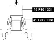
Oil Seal (Side gear) Assembly Note
1. Apply differential oil to the new oil seal lip.
2. Assemble the oil seal using the SSTs.
ac5jjw00003284
|
Oil Seal (Coupling component) Assembly Note
1. Apply differential oil to the new oil seal lip.
2. Assemble the oil seal using the SSTs.
ac5jjw00003285
|
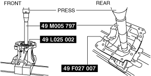
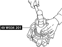
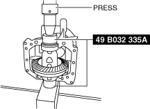
Rear Cover Assembly Note
1. Clean the alignment surface of the carrier and rear cove.
2. Apply pressure to the case using a press and install the rear cover using the SSTs (49 B032 335A) as shown in the figure.
am6xuw00011653
|
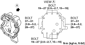
3. Install the bolts with the specified torque as shown in the figure.
am6xuw00011654
|