 |
ac5wzn00001165
SHIFT AND SELECT MECHANISM [C66M-R]
id0515m8283900
Purpose, Function
Construction
ac5wzn00001165
|
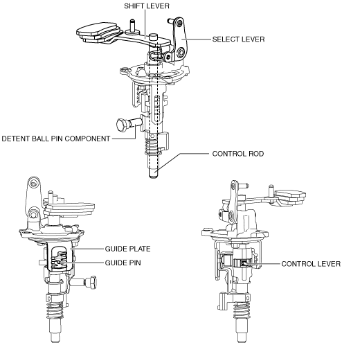
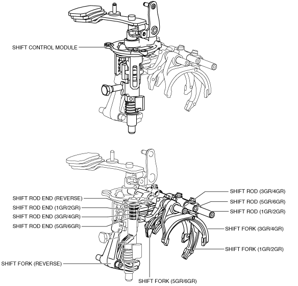
Shift control module
ac5wzn00001166
|
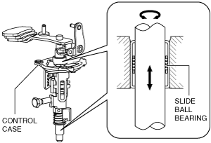
Slide ball bearing
ac5wzn00001167
|
Operation
1GR
ac5wzn00001168
|
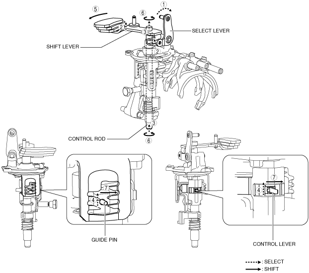
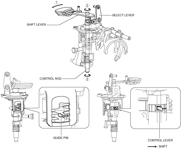
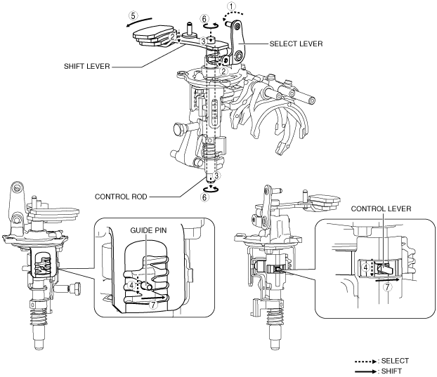
1. When the shift lever in the cabin is tilted to the left to shift to 1GR, the select lever moves in the direction of arrow 1 shown in the figure.
2. Following the movement of the select lever, the shift lever moves in the direction of arrow 2 shown in the figure.
3. Following the movement of the select lever, the shift lever moves in the direction of arrow 3 shown in the figure.
4. Following the movement of the select lever, the control lever and the guide pin move in the direction of arrow 4 shown in the figure.
5. When the shift lever in the cabin is tilted forward to shift to 1GR, the shift lever in the engine compartment moves in the direction of arrow 5 shown in the figure.
6. Following the movement of the shift lever in the engine compartment, the control rod moves in the direction of arrow 6 shown in the figure.
7. Following the movement of the shift lever in the engine compartment, the control lever and the guide pin move in the direction of arrow 7 shown in the figure.
ac5wzn00001169
|
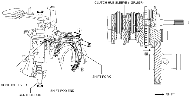
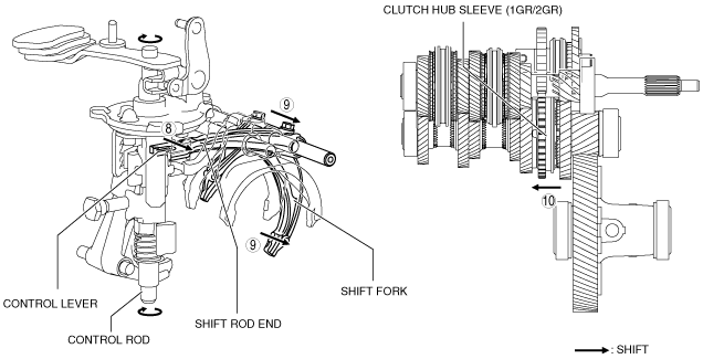
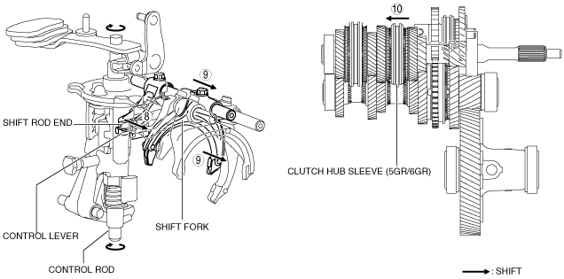
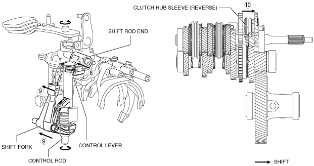
8. Because the control rod turns with the control lever, the control lever pushes the shift rod end and moves it in the direction of arrow 8 shown in the figure.
9. The shift rod end and the shift fork are integrated with the shift rod. Therefore, the movement of the shift rod end is transmitted to the shift fork via the shift rod, and the shift fork moves in the direction of arrow 9.
10. The shift fork moves the clutch hub sleeve in the direction of arrow 10 shown in the figure.
11. The shift change to 1GR is completed.
2GR
ac5wzn00001170
|
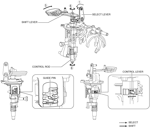
1. When the shift lever in the cabin is tilted to the left to shift to 2GR, the select lever moves in the direction of arrow 1 shown in the figure.
2. Following the movement of the select lever, the shift lever moves in the direction of arrow 2 shown in the figure.
3. Following the movement of the select lever, the shift lever moves in the direction of arrow 3 shown in the figure.
4. Following the movement of the select lever, the control lever and the guide pin move in the direction of arrow 4 shown in the figure.
5. When the shift lever in the cabin is tilted rearward to shift to 2GR, the shift lever in the engine compartment moves in the direction of arrow 5 shown in the figure.
6. Following the movement of the shift lever in the engine compartment, the control rod moves in the direction of arrow 6 shown in the figure.
7. Following the movement of the shift lever in the engine compartment, the control lever and the guide pin move in the direction of arrow 7 shown in the figure.
ac5wzn00001171
|
8. Because the control rod turns with the control lever, the control lever pushes the shift rod end and moves it in the direction of arrow 8 shown in the figure.
9. The shift rod end and the shift fork are integrated with the shift rod. Therefore, the movement of the shift rod end is transmitted to the shift fork via the shift rod, and the shift fork moves in the direction of arrow 9.
10. The shift fork moves the clutch hub sleeve in the direction of arrow 10 shown in the figure.
11. The shift change to 2GR is completed.
3GR
ac5wzn00001172
|
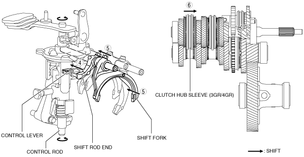
1. When the shift lever in the cabin is tilted forward to shift to 3GR, the shift lever in the engine compartment moves in the direction of arrow 1 shown in the figure.
2. Following the movement of the shift lever in the engine compartment, the control rod moves in the direction of arrow 2 shown in the figure.
3. Following the movement of the shift lever in the engine compartment, the control lever and the guide pin move in the direction of arrow 3 shown in the figure.
ac5wzn00001173
|
4. Because the control rod turns with the control lever, the control lever pushes the shift rod end and moves it in the direction of arrow 4 shown in the figure.
5. The shift rod end and the shift fork are integrated with the shift rod. Therefore, the movement of the shift rod end is transmitted to the shift fork via the shift rod, and the shift fork moves in the direction of arrow 5.
6. The shift fork moves the clutch hub sleeve in the direction of arrow 6 shown in the figure.
7. The shift change to 3GR is completed.
4GR
ac5wzn00001174
|
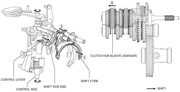
1. When the shift lever in the cabin is tilted rearward to shift to 4GR, the shift lever in the engine compartment moves in the direction of arrow 1 shown in the figure.
2. Following the movement of the shift lever in the engine compartment, the control rod moves in the direction of arrow 2 shown in the figure.
3. Following the movement of the shift lever in the engine compartment, the control lever and the guide pin move in the direction of arrow 3 shown in the figure.
ac5wzn00001175
|
4. Because the control rod turns with the control lever, the control lever pushes the shift rod end and moves it in the direction of arrow 4 shown in the figure.
5. The shift rod end and the shift fork are integrated with the shift rod. Therefore, the movement of the shift rod end is transmitted to the shift fork via the shift rod, and the shift fork moves in the direction of arrow 5.
6. The shift fork moves the clutch hub sleeve in the direction of arrow 6 shown in the figure.
7. The shift change to 4GR is completed.
5GR
ac5wzn00001176
|
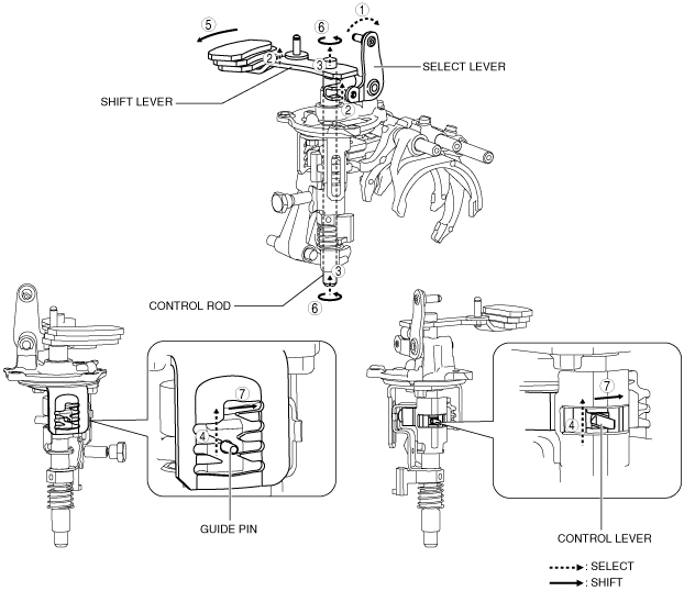
1. When the shift lever in the cabin is tilted to the right to shift to 5GR, the select lever moves in the direction of arrow 1 shown in the figure.
2. Following the movement of the select lever, the shift lever moves in the direction of arrow 2 shown in the figure.
3. Following the movement of the select lever, the shift lever moves in the direction of arrow 3 shown in the figure.
4. Following the movement of the select lever, the control lever and the guide pin move in the direction of arrow 4 shown in the figure.
5. When the shift lever in the cabin is tilted forward to shift to 5GR, the shift lever in the engine compartment moves in the direction of arrow 5 shown in the figure.
6. Following the movement of the shift lever in the engine compartment, the control rod moves in the direction of arrow 6 shown in the figure.
7. Following the movement of the shift lever in the engine compartment, the control lever and the guide pin move in the direction of arrow 7 shown in the figure.
ac5wzn00001177
|
8. Because the control rod turns with the control lever, the control lever pushes the shift rod end and moves it in the direction of arrow 8 shown in the figure.
9. The shift rod end and the shift fork are integrated with the shift rod. Therefore, the movement of the shift rod end is transmitted to the shift fork via the shift rod, and the shift fork moves in the direction of arrow 9.
10. The shift fork moves the clutch hub sleeve in the direction of arrow 10 shown in the figure.
11. The shift change to 5GR is completed.
6GR
ac5wzn00001178
|
1. When the shift lever in the cabin is tilted to the right to shift to 6GR, the select lever moves in the direction of arrow 1 shown in the figure.
2. Following the movement of the select lever, the shift lever moves in the direction of arrow 2 shown in the figure.
3. Following the movement of the select lever, the shift lever moves in the direction of arrow 3 shown in the figure.
4. Following the movement of the select lever, the control lever and the guide pin move in the direction of arrow 4 shown in the figure.
5. When the shift lever in the cabin is tilted rearward to shift to 6GR, the shift lever in the engine compartment moves in the direction of arrow 5 shown in the figure.
6. Following the movement of the shift lever in the engine compartment, the control rod moves in the direction of arrow 6 shown in the figure.
7. Following the movement of the shift lever in the engine compartment, the control lever and the guide pin move in the direction of arrow 7 shown in the figure.
ac5wzn00001179
|
8. Because the control rod turns with the control lever, the control lever pushes the shift rod end and moves it in the direction of arrow 8 shown in the figure.
9. The shift rod end and the shift fork are integrated with the shift rod. Therefore, the movement of the shift rod end is transmitted to the shift fork via the shift rod, and the shift fork moves in the direction of arrow 9.
10. The shift fork moves the clutch hub sleeve in the direction of arrow 10 shown in the figure.
11. The shift change to 6GR is completed.
Reverse
ac5wzn00001180
|
1. When the shift lever in the cabin is tilted to the left to shift to the reverse gear, the select lever moves in the direction of arrow 1 shown in the figure.
2. Following the movement of the select lever, the shift lever moves in the direction of arrow 2 shown in the figure.
3. Following the movement of the select lever, the shift lever moves in the direction of arrow 3 shown in the figure.
4. Following the movement of the select lever, the control lever and the guide pin move in the direction of arrow 4 shown in the figure.
5. When the shift lever in the cabin is tilted forward to shift to the reverse gear, the shift lever in the engine compartment moves in the direction of arrow 5 shown in the figure.
6. Following the movement of the shift lever in the engine compartment, the control rod moves in the direction of arrow 6 shown in the figure.
7. Following the movement of the shift lever in the engine compartment, the control lever and the guide pin move in the direction of arrow 7 shown in the figure.
ac5wzn00001181
|
8. Because the control rod turns with the control lever, the control lever pushes the shift rod end and moves it in the direction of arrow 8 shown in the figure.
9. The shift rod end and the shift fork are integrated with the shift rod. Therefore, the movement of the shift rod end is transmitted to the shift fork via the shift rod, and the shift fork moves in the direction of arrow 9.
10. The shift fork moves the clutch hub sleeve in the direction of arrow 10 shown in the figure.
11. The shift change to the reverse gear is completed.