 |
ac5uuw00002145
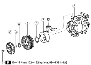
MAGNETIC CLUTCH DISASSEMBLY/ASSEMBLY [SKYACTIV-G 2.5T]
id071100006343
Replacement Part
|
Bolt
Quantity: 1
Location of use: Magnetic clutch
|
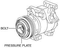
Magnetic Clutch is Disassembled/Assembled with A/C Compressor Removed from Vehicle
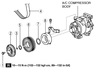
1. Disassemble in the order indicated in the table.
ac5uuw00002145
|
|
1
|
Bolt
|
|
2
|
Pressure plate
|
|
3
|
Shim
|
|
4
|
Snap ring
|
|
5
|
A/C compressor pulley
|
|
6
|
Snap ring
|
|
7
|
Stator
|
|
8
|
A/C compressor body
|
2. Assemble in the reverse order of disassembly.
3. Adjust the magnetic clutch clearance. (See MAGNETIC CLUTCH ADJUSTMENT [SKYACTIV-G 2.5T].)
Bolt removal/installation note
1. When removing or installing the bolt, lock the A/C compressor pulley against rotation using the following procedure.
ac5uuw00001184
|
ac5uuw00001185
|
2. When installing a new A/C compressor body, replace the recommended bolt.
Magnetic Clutch is Disassembled/Assembled with A/C Compressor Equipped to Vehicle
1. Remove the following parts:
2. Bend back the front under cover No.1. (See FRONT UNDER COVER No.1 REMOVAL/INSTALLATION.)
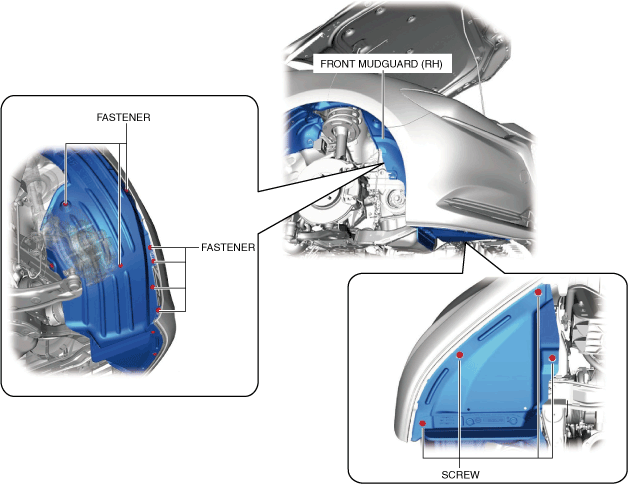
3. Remove screws.
am6xuw00009419
|
4. Remove the fasteners.
5. Bend back the front side of the front mudguard (RH) in the direction of the arrow shown in the figure.
am6xuw00009420
|
6. Disassemble in the order indicated in the table.
ac5wzw00006020
|
|
1
|
Bolt
|
|
2
|
Pressure plate
|
|
3
|
Shim
|
|
4
|
Drive Belt
|
|
5
|
Snap ring
|
|
6
|
A/C compressor pulley
|
|
7
|
Snap ring
|
|
8
|
Stator
|
7. Assemble in the reverse order of disassembly.
8. Adjust the magnetic clutch clearance. (See MAGNETIC CLUTCH ADJUSTMENT [SKYACTIV-G 2.5T].)
Bolt removal/installation note
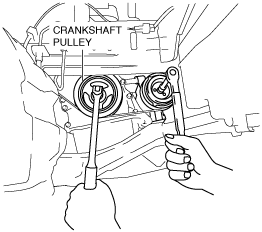
1. When removing or installing the bolt, lock the A/C compressor pulley against rotation using the following procedure.
2. Secure the crankshaft pulley.
ac5uuw00003876
|
3. Remove the bolt with the pressure plate secured.
ac5wzw00006022
|
am6xuw00009421
|
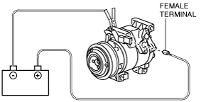
4. Turn the A/C relay off using the "ACCS" simulation function.
Stator removal/installation note
1. Disconnect the negative battery terminal. (See NEGATIVE BATTERY TERMINAL DISCONNECTION/CONNECTION.)
2. Disconnect the magnetic clutch connector.
ac5wzw00006025
|
3. Remove the bolts A, B, and C.
ac5wzw00006026
|
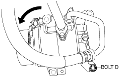
4. Loose bolt D approx. 5 mm {0.2 in}.
5. Tilt the A/C compressor centered around bolt D.
ac5wzw00006027
|
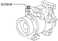
6. Remove the screw.
ac5wzw00006028
|
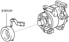
7. Remove the stator.
ac5wzw00006029
|