 |
am6zzw00015959
A/C UNIT DISASSEMBLY/ASSEMBLY
id071100800300
Replacement Part
|
O-ring (expansion valve)
Quantity: 2
Location of use: expansion valve
|
L.H.D.
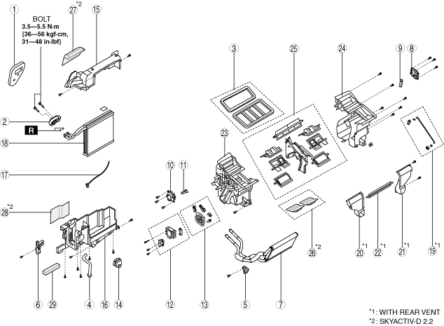
1. Disassemble in the order indicated in the table.
am6zzw00015959
|
|
Step |
Part name |
Disassembly/assembly of main parts |
||
|---|---|---|---|---|
|
Heater core |
Evaporator temperature sensor |
Evaporator |
||
|
1
|
Polyurethane foam
|
X
|
X
|
X
|
|
2
|
Expansion valve
|
-
|
-
|
X
|
|
3
|
Adhesive polyurethane
|
-
|
-
|
-
|
|
4
|
Drain hose
|
-
|
-
|
-
|
|
5
|
Plate (1)
|
X
|
X
|
X
|
|
6
|
Plate (2)
|
X
|
X
|
X
|
|
7
|
Heater core
|
X
|
X
|
X
|
|
8
|
Driver-side air mix actuator
|
-
|
-
|
-
|
|
9
|
Driver-side air mix link
|
-
|
-
|
-
|
|
10
|
Passenger-side air mix actuator
|
-
|
-
|
-
|
|
11
|
Passenger-side air mix link
|
-
|
-
|
-
|
|
12
|
Airflow mode actuator
|
-
|
-
|
-
|
|
13
|
Airflow mode link set
|
-
|
-
|
-
|
|
14
|
PTC heater (SKYACTIV-D 2.2 (with PTC heater))
|
-
|
-
|
-
|
|
15
|
Blower fan controller
|
-
|
-
|
-
|
|
16
|
A/C case (1)
|
-
|
X
|
X
|
|
17
|
A/C case (2)
|
-
|
X
|
X
|
|
18
|
Evaporator temperature sensor (See Evaporator temperature sensor assembly note.)
|
-
|
X
|
X
|
|
19
|
Evaporator
|
-
|
-
|
X
|
|
20
|
Airflow mode link set (with rear vent)
|
-
|
-
|
-
|
|
21
|
A/C case (rear vent (1)) (with rear vent)
|
-
|
-
|
-
|
|
22
|
A/C case (rear vent (2)) (with rear vent)
|
-
|
-
|
-
|
|
23
|
Door damper (with rear vent)
|
-
|
-
|
-
|
|
24
|
A/C case (3)
|
-
|
-
|
-
|
|
25
|
A/C case (4)
|
-
|
-
|
-
|
|
26
|
Door damper
|
-
|
-
|
-
|
|
27
|
Adhesive polyurethane
|
-
|
-
|
-
|
|
28
|
Adhesive polyurethane (SKYACTIV-D 2.2)
|
-
|
-
|
-
|
|
29
|
Rubber (SKYACTIV-D 2.2)
|
-
|
-
|
-
|
|
30
|
Rubber (SKYACTIV-D 2.2)
|
-
|
-
|
-
|
|
31
|
Adhesive polyurethane (SKYACTIV-D 2.2)
|
-
|
-
|
-
|
|
32
|
Thinsulate (SKYACTIV-D 2.2)
|
-
|
-
|
-
|
2. Assemble in the reverse order of disassembly.
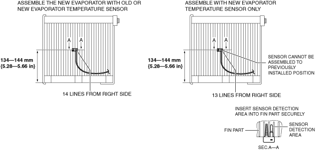
Evaporator temperature sensor assembly note
1. Assemble the evaporator temperature sensor as shown in the figure.
am6zzw00015960
|
R.H.D.
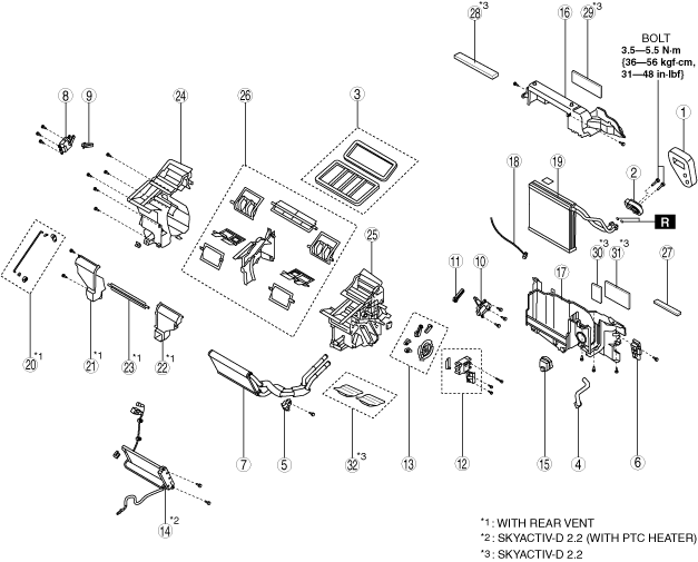
1. Disassemble in the order indicated in the table.
am6zzw00015961
|
|
Step |
Part name |
Disassembly/assembly of main parts |
||
|---|---|---|---|---|
|
Heater core |
Evaporator temperature sensor |
Evaporator |
||
|
1
|
Polyurethane foam
|
X
|
X
|
X
|
|
2
|
Expansion valve
|
-
|
-
|
X
|
|
3
|
Adhesive polyurethane
|
-
|
-
|
-
|
|
4
|
Drain hose
|
-
|
-
|
-
|
|
5
|
Plate (1)
|
X
|
X
|
X
|
|
6
|
Plate (2)
|
X
|
X
|
X
|
|
7
|
Heater core
|
X
|
X
|
X
|
|
8
|
Driver-side air mix actuator
|
-
|
-
|
-
|
|
9
|
Driver-side air mix link
|
-
|
-
|
-
|
|
10
|
Passenger-side air mix actuator
|
-
|
-
|
-
|
|
11
|
Passenger-side air mix link
|
-
|
-
|
-
|
|
12
|
Airflow mode actuator
|
-
|
-
|
-
|
|
13
|
Airflow mode link set
|
-
|
-
|
-
|
|
14
|
Blower fan controller
|
-
|
-
|
-
|
|
15
|
A/C case (1)
|
-
|
X
|
X
|
|
16
|
A/C case (2)
|
-
|
X
|
X
|
|
17
|
Evaporator temperature sensor (See Evaporator temperature sensor assembly note.)
|
-
|
X
|
X
|
|
18
|
Evaporator
|
-
|
-
|
X
|
|
19
|
Airflow mode link set (with rear vent)
|
-
|
-
|
-
|
|
20
|
A/C case (rear vent (1)) (with rear vent)
|
-
|
-
|
-
|
|
21
|
A/C case (rear vent (2)) (with rear vent)
|
-
|
-
|
-
|
|
22
|
Door damper (with rear vent)
|
-
|
-
|
-
|
|
23
|
A/C case (3)
|
-
|
-
|
-
|
|
24
|
A/C case (4)
|
-
|
-
|
-
|
|
25
|
Door damper
|
-
|
-
|
-
|
|
26
|
Thinsulate (SKYACTIV-D 2.2)
|
-
|
-
|
-
|
|
27
|
Thinsulate (SKYACTIV-D 2.2)
|
-
|
-
|
-
|
|
28
|
Thinsulate (SKYACTIV-D 2.2)
|
-
|
-
|
-
|
|
29
|
Adhesive polyurethane
|
-
|
-
|
-
|
2. Assemble in the reverse order of disassembly.
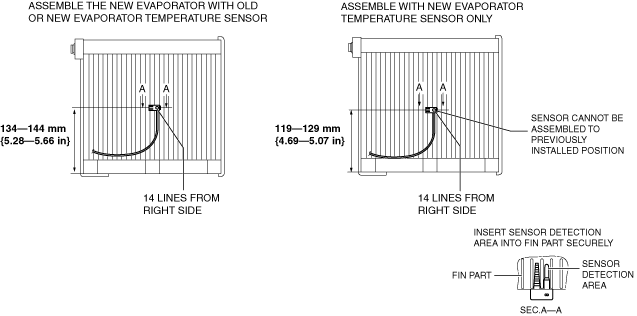
Evaporator temperature sensor assembly note
1. Assemble the evaporator temperature sensor as shown in the figure.
am6zzw00015962
|