|
1
|
INSPECT BRAKE SWITCH CONNECTOR
• Switch the ignition off.
• Disconnect the negative battery terminal.
• Disconnect the brake switch connector.
• Inspect the connector engagement and connection condition and inspect the terminals for damage, deformation, corrosion, or disconnection.
• Is the connector normal?
|
Yes
|
Go to the next step.
|
|
No
|
Repair or replace the connector, then go to Step 7.
|
|
2
|
INSPECT BRAKE SWITCH (NO.1 SIGNAL)
• Inspect the brake switch (No.1 signal).
• Is the brake switch (No.1 signal) normal?
|
Yes
|
Go to the next step.
|
|
No
|
Replace the brake switch, then go to Step 7.
|
|
3
|
INSPECT FOR OPEN CIRCUIT OR SHORT TO GROUND IN BRAKE SWITCH (NO.1 SIGNAL) POWER SUPPLY CIRCUIT
• Verify that the brake switch connector is disconnected.
• Reconnect the negative battery terminal.
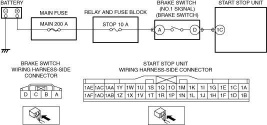
• Measure the voltage at the brake switch terminal A (wiring harness-side).
• Is the voltage B+?
|
Yes
|
Go to the next step.
|
|
No
|
Inspect the STOP 10 A fuse and MAIN 200 A fuse.
• If the fuse is blown:
-
― Refer to the wiring diagram and verify whether or not there is a common connector between MAIN 200 A fuse and brake switch terminal A.
If there is a common connector:
-
• Determine the malfunctioning part by inspecting the common connector and the terminal for corrosion, damage, or pin disconnection, and the common wiring harness for a short to ground.
• Repair or replace the malfunctioning part.
If there is no common connector:
-
• Repair or replace the wiring harness which has a short to ground.
• Replace the fuse.
• If the fuse is damaged:
-
― Replace the fuse.
• If the fuse is normal:
-
― Refer to the wiring diagram and verify whether or not there is a common connector between battery positive terminal and brake switch terminal A.
If there is a common connector:
-
• Determine the malfunctioning part by inspecting the common connector and the terminal for corrosion, damage, or pin disconnection, and the common wiring harness for an open circuit.
• Repair or replace the malfunctioning part.
If there is no common connector:
-
• Repair or replace the wiring harness which has an open circuit.
Go to Step 7.
|
|
4
|
INSPECT START STOP UNIT CONNECTOR
• Disconnect the negative battery terminal.
• Disconnect the start stop unit connector.
• Inspect the connector engagement and connection condition and inspect the terminals for damage, deformation, corrosion, or disconnection.
• Is the connector normal?
|
Yes
|
Go to the next step.
|
|
No
|
Repair or replace the connector, then go to Step 7.
|
|
5
|
INSPECT FOR SHORT TO GROUND IN BRAKE SWITCH (NO.1 SIGNAL) CIRCUIT
• Verify that the brake switch and start stop unit connectors are disconnected.
• Inspect for continuity between brake switch terminal D (wiring harness-side) and body ground.
• Is there continuity?
|
Yes
|
Refer to the wiring diagram and verify whether or not there is a common connector between brake switch terminal D and start stop unit terminal 1C.
If there is a common connector:
• Determine the malfunctioning part by inspecting the common connector and the terminal for corrosion, damage, or pin disconnection, and the common wiring harness for a short to ground.
• Repair or replace the malfunctioning part.
If there is no common connector:
• Repair or replace the wiring harness which has a short to ground.
Go to Step 7.
|
|
No
|
Go to the next step.
|
|
6
|
INSPECT FOR OPEN CIRCUIT IN BRAKE SWITCH (NO.1 SIGNAL) CIRCUIT
• Verify that the brake switch and start stop unit connectors are disconnected.
• Inspect for continuity between brake switch terminal D (wiring harness-side) and start stop unit terminal 1C (wiring harness-side).
• Is there continuity?
|
Yes
|
Go to the next step.
|
|
No
|
Refer to the wiring diagram and verify whether or not there is a common connector between brake switch terminal D and start stop unit terminal 1C.
If there is a common connector:
• Determine the malfunctioning part by inspecting the common connector and the terminal for corrosion, damage, or pin disconnection, and the common wiring harness for an open circuit.
• Repair or replace the malfunctioning part.
If there is no common connector:
• Repair or replace the wiring harness which has an open circuit.
Go to the next step.
|
|
7
|
VERIFY THAT REPAIRS HAVE BEEN COMPLETED
• Always reconnect all disconnected connectors.
• Reconnect the negative battery terminal.
• Clear the DTC for the start stop unit using the M-MDS.
• Perform the work of depressing the brake pedal for 3 s or more and then releasing it for 5 times or more with the ignition switched ON (engine off or on).
• Retrieve the start stop unit DTCs using the M-MDS.
• Is the same Pending DTC present?
|
Yes
|
Repeat the inspection from Step 1.
• If the malfunction recurs, replace the start stop unit.
Go to the next step.
|
|
No
|
Go to the next step.
|
|
8
|
VERIFY IF OTHER DTCs DISPLAYED
• Are any other DTCs displayed?
|
Yes
|
Repair or replace the malfunctioning part according to the applicable DTC troubleshooting.
|
|
No
|
DTC troubleshooting completed.
|