POWER OUTER MIRROR SYSTEM
id091200013500
Outline
• The driver can operate the outer mirrors remotely by operating the power outer mirror switch.
• The driver can operate the outer mirror retract/return by operating the power outer mirror switch and the retract/return switch. (With retractable power outer mirrors)
• When the driver locks/unlocks the doors, the power outer mirrors retract/return in conjunction with the door lock/unlock operation. (With outer mirror automatic folding)
Function
Outer mirror glass adjustment function
-
• Outer mirror glass can be adjusted up/down and left/right electrically by operating the power outer mirror switch.
Automatic retract/return function
-
• When the power outer mirror control module detects door lock/unlock, it retracts/returns the power outer mirrors.
IG OFF timer function
-
• Adjustment and retract/return of the outer mirror glass can be performed by operating the power outer mirror switch for approx. 40 s after switching the ignition from ON (engine off or on) to off.
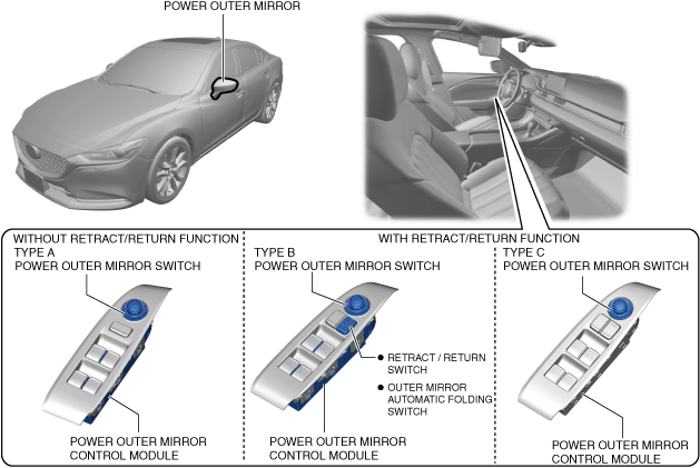
Structural View
System Wiring Diagram
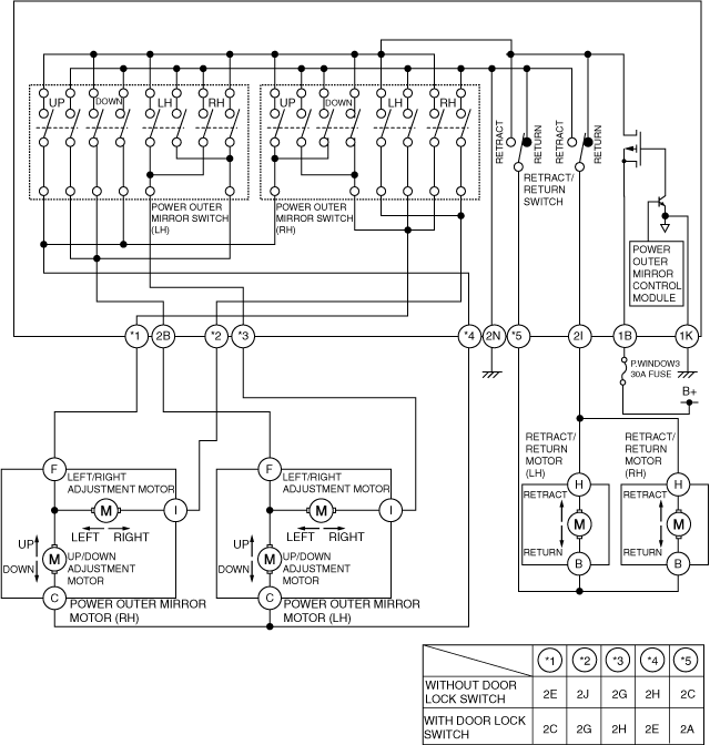
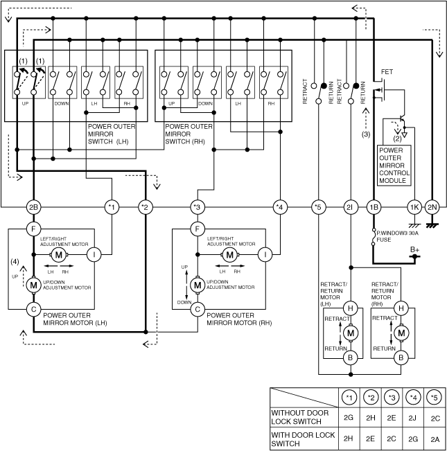
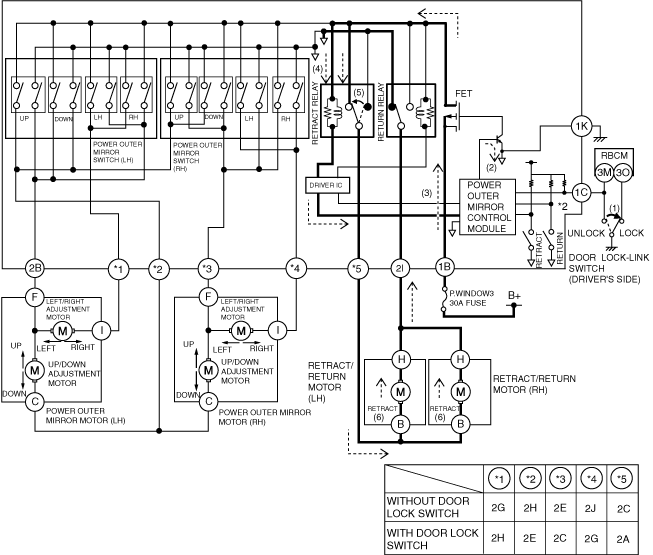
With retract/return function (Without automatic retract/return function)
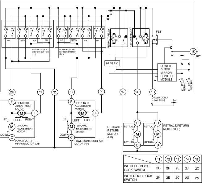
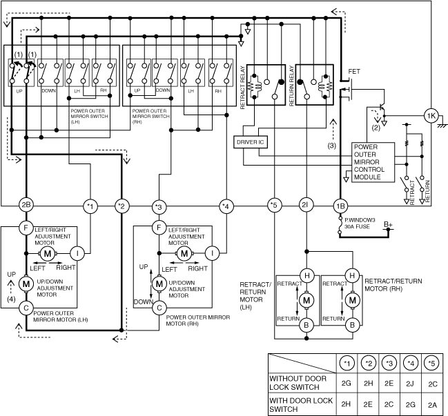
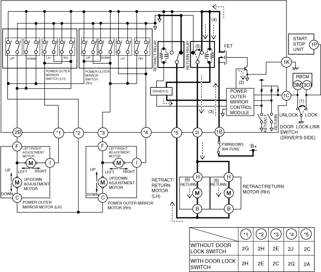
With retract/return function (With automatic retract/return function)
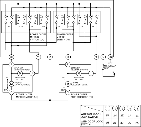
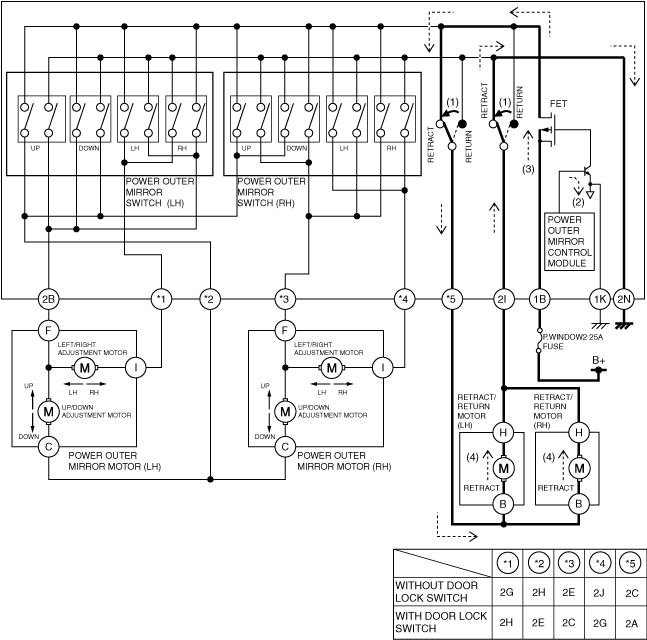
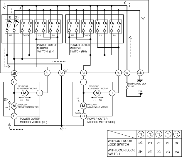
Without retract/return function
Operation (With retract/return function)
Outer mirror glass adjustment operation (Example: adjusting left outer mirror upward)
-
Without automatic retract/return function
-
• When the upward switch is turned on (1), the power outer mirror control module turns the transistor on (2).
• The FET turns on when the transistor turns on and current flows (3).
• When the FET turns on, the up/down adjustment motor operates upward (4) and the outer mirror operates upward.
-
With automatic retract/return function
-
1. When the upward switch is turned on (1), current from the power outer mirror control module to the transistor flows and the transistor turns on.
2. The FET turns on when the transistor turns on and current flows (2).
3. With current flowing, the up/down adjustment motor moves in the upward direction (3).
Outer mirror glass retract/return operation (Example: retracting outer mirrors)
-
Without automatic retract/return function
-
• When the switch is turned on (1) for retracting direction, the power outer mirror control module turns the transistor on (2).
• The FET turns on when the transistor turns on and current flows (3).
• When the FET turns on, the retract/return motor operates in the retracting direction (4) and the outer mirrors retract.
-
With automatic retract/return function
-
1. When the retract side of the retract/return switch is turned on (1), the power outer mirror control module turns the transistor on (2).
2. The FET turns on when the transistor turns on and current flows (3).
3. When the FET turns on, current flows (4) to the retract relay coil and the retract relay turns on (5).
4. When the retract relay turns on, the retract/return motor operates (6) in the retract direction and the outer mirrors retract.
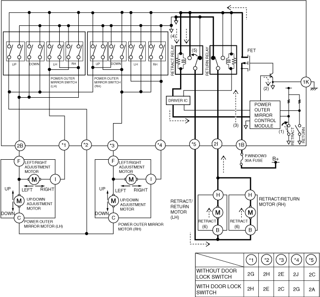
Power outer mirror retract operation (With automatic retract/return function) (Example: Retracting power outer mirrors automatically)
-
Operation condition
-
• The power outer mirrors retract when the driver's door is locked with all of the following conditions met.
-
― Outer mirror automatic folding switch is in AUTO position
― Ignition switched OFF
― Driver's door is unlocked
-
1. When the power outer mirror control module detects (1) a lock signal, it turns the transistor on (2).
2. The FET turns on when the transistor turns on and current flows (3).
3. When the FET turns on, current flows (4) to the retract relay coil and the retract relay turns on (5).
4. When the retract relay turns on, the retract/return motor operates (6) in the retract direction and the power outer mirrors retract.
Power outer mirror return operation (With automatic retract/return function) (Example: Returning power outer mirrors automatically)
-
Operation condition
-
• The power outer mirrors return when the driver's door is unlocked or the ignition is switched ON (engine off or on) with all of the following conditions met.
-
― Outer mirror automatic folding switch is in AUTO position
― Ignition switched OFF
― Driver's door is locked
-
1. When the power outer mirror control module detects (1) an unlock signal or the ignition switched ON (engine off or on), it turns the transistor on (2).
2. The FET turns on when the transistor turns on and current flows (3).
3. When the FET turns on, current flows (4) to the return relay coil and the return relay turns on (5).
4. When the return relay turns on, the retract/return motor operates (6) in the return direction and the power outer mirrors return.
IG OFF timer operation
-
• When the ignition is switched from ON (engine off or on) to OFF, the IG OFF timer function inside the power outer mirror control module is turned on and the power outer mirror switch can be operated for approx. 40 s after IG OFF is detected.
Operation (Without retractable outer mirror)
Outer mirror glass adjustment operation (Example: adjusting left outer mirror upward)
-
• When the upward switch turns on (1), the up/down adjustment motor operates upward (2) and the outer mirror operates upward.
IG OFF timer operation
-
• When the ignition is switched from ON (engine off or on) to OFF, the IG OFF timer function inside the power outer mirror control module is turned on and the power outer mirror switch can be operated for approx. 40 s after IG OFF is detected.
Fail-safe
• Not applicable