|
am6zzw00016488
FRONT SEAT REMOVAL/INSTALLATION
id091300800200
Driver's Side
1. Disconnect the negative battery terminal and wait for 1 min or more. (Without power seat system) (See NEGATIVE BATTERY TERMINAL DISCONNECTION/CONNECTION.)
2. Remove the head restraint.
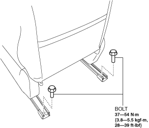
3. Slide the front seat to the positions where the bolts shown in the figure can be removed.
4. Remove the bolts.
am6zzw00016488
|
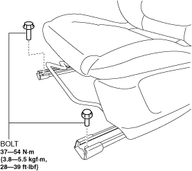
5. Slide the front seat to the positions where the bolts shown in the figure can be removed.
6. Remove the bolts.
am6xuw00009765
|
7. Disconnect the negative battery terminal and wait for 1 min. or more. (With power seat system) (See NEGATIVE BATTERY TERMINAL DISCONNECTION/CONNECTION.)
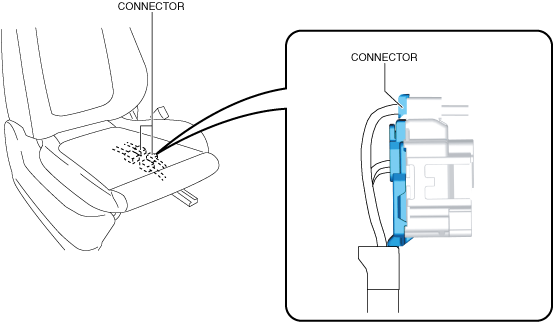
8. Disconnect the connector. (with position memory system).
am6zzw00013643
|
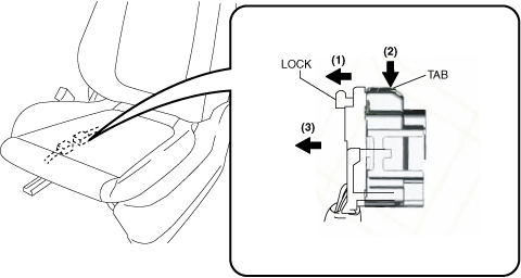
9. Slide the lock in the direction of arrow (1) shown in the figure, and while pressing the tab in the direction of arrow (2), disconnect the connector in the direction of arrow (3).
am6zzw00013642
|
10. Remove the front seat.
11. Install in the reverse order of removal.
Passenger's Side
1. Disconnect the negative battery terminal and wait for 1 min or more. (Without power seat system) (See NEGATIVE BATTERY TERMINAL DISCONNECTION/CONNECTION.)
2. Remove the head restraint.
3. Slide the front seat to the positions where the bolts shown in the figure can be removed.
4. Remove the bolts.
am6xuw00013151
|
5. Slide the front seat to the positions where the bolts shown in the figure can be removed.
6. Remove the bolts.
am6xuw00009765
|
7. Disconnect the negative battery terminal and wait for 1 min. or more. (With power seat system) (See NEGATIVE BATTERY TERMINAL DISCONNECTION/CONNECTION.)
8. Slide the lock in the direction of arrow (1) shown in the figure, and while pressing the tab in the direction of arrow (2), disconnect the connector in the direction of arrow (3).
am6zzw00013644
|
9. Install in the reverse order of removal.
10. When the passenger's seat is removed, perform the DTC inspection for the SAS control module using the M-MDS and verify that no DTCs are displayed. (See DTC INSPECTION [SAS CONTROL MODULE (TWO-STEP DEPLOYMENT CONTROL SYSTEM)].)
11. When the passenger's seat is replaced with a new one, perform the occupant classification sensor calibration using the M-MDS. (See OCCUPANT CLASSIFICATION SENSOR CALIBRATION [TWO-STEP DEPLOYMENT CONTROL SYSTEM].)