 |
am6zzn00005497
WINDSHIELD WIPER/WASHER SYSTEM
id091900001900
Outline
Function
Structure/Construction
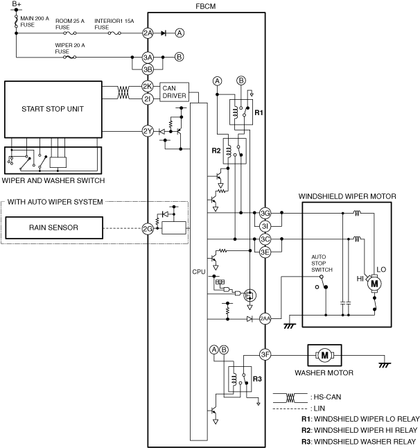
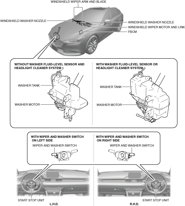
System structure
am6zzn00005497
|
System wiring diagram
am6zzn00005498
|
Operation
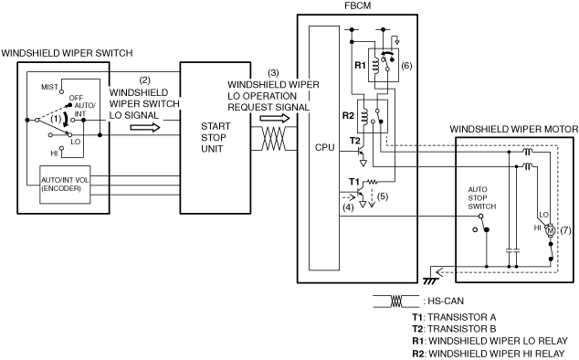
Continuous wiper (low) operation
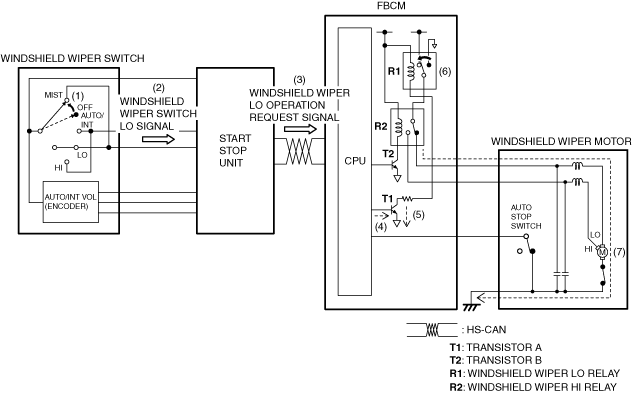
1. When the windshield wiper switch is in the LO position (1) with the ignition switched ON (engine off or on), the start stop unit detects (2) windshield wiper switch LO signal.
2. When the start stop unit detects the windshield wiper switch LO signal, the windshield wiper LO operation request signal is sent (3) to the front body control module (FBCM) by CAN communication.
3. When the front body control module (FBCM) receives the windshield wiper LO operation request signal, it turns transistor A on (4).
4. When transistor A turns on, a ground circuit with the windshield wiper LO relay is established (5), and the windshield wiper LO relay turns on (6).
5. When the windshield wiper LO relay turns on, the windshield wipers operate continuously at low speed (7).
am6xun00003961
|
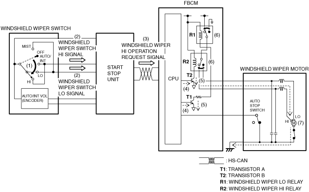
Continuous wiper (high) operation
1. When the windshield wiper switch is in the HI position (1) with the ignition switched ON (engine off or on), the start stop unit detects (2) windshield wiper switch LO and HI signals.
2. When the start stop unit detects the windshield wiper switch LO and HI signals, the windshield wiper HI operation request signal is sent (3) to the front body control module (FBCM) by CAN communication.
3. When the front body control module (FBCM) receives the windshield wiper HI operation request signal, it turns transistors A and B on (4).
4. When transistors A and B turn on, a ground circuits with the windshield wiper LO relay and the windshield wiper HI relay are established (5), and the windshield wiper LO relay and windshield wiper HI relay turn on (6).
5. When the windshield wiper LO relay and windshield wiper HI relay turn on, windshield wipers operate continuously at high speed (7).
am6xun00003962
|
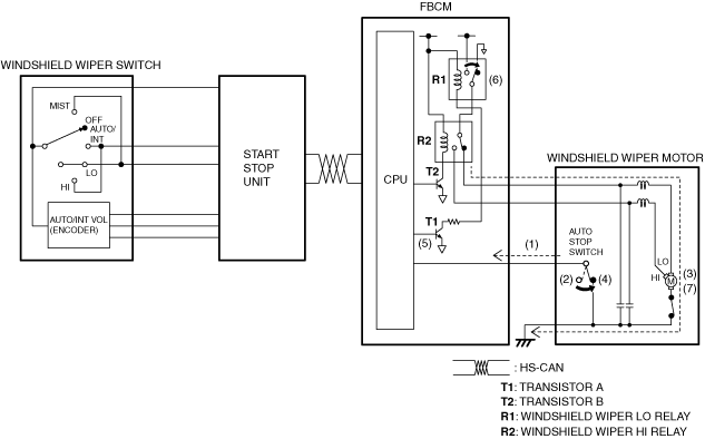
Auto-stop operation
am6xun00003963
|
One-touch wiper operation
1. When the windshield wiper switch is moved up (MIST position) (1) with the ignition switched ON (engine off or on), the start stop unit detects (2) windshield wiper switch LO signal.
2. When the start stop unit detects the windshield wiper switch LO signal, the windshield wiper LO operation request signal is sent (3) to the front body control module (FBCM) by CAN communication.
3. When the front body control module (FBCM) receives the windshield wiper LO operation request signal, it turns transistor A on (4).
4. When transistor A turns on, a ground circuit with the windshield wiper LO relay is established (5), and the windshield wiper LO relay turns on (6).
5. When the windshield wiper LO relay turns on, the windshield wipers operate at low speed (7).
am6xun00003964
|
Intermittent wiper operation (without auto wiper system)
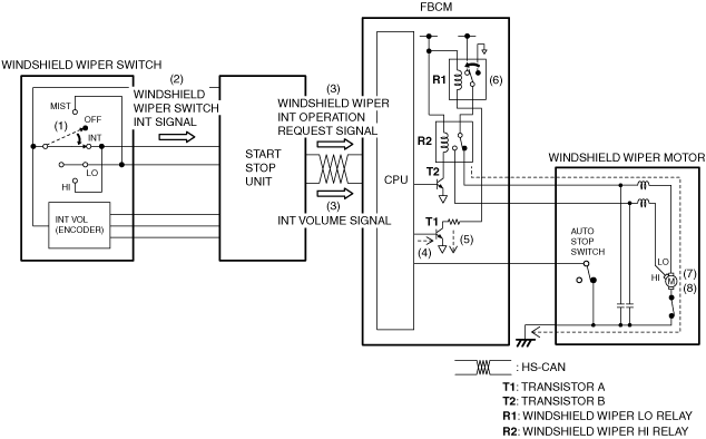
1. When the windshield wiper switch is in the INT position (1) with the ignition switched ON (engine off or on), the start stop unit detects (2) windshield wiper switch INT signal.
2. When the start stop unit detects the windshield wiper switch INT signal, the windshield wiper INT operation request signal and the INT volume signal are sent (3) to the front body control module (FBCM) by CAN communication.
3. When the front body control module (FBCM) receives the windshield wiper INT operation request signal, it turns transistor A on (4).
4. When transistor A turns on, a ground circuit with the windshield wiper LO relay is established (5), and the windshield wiper LO relay turns on (6).
5. When the windshield wiper LO relay turns on, the windshield wipers operate at low speed (7).
6. When the windshield wipers stop at the park position due to the auto stop operation and after a certain period of time has elapsed, which was calculated based on the INT volume signal, the front body control module (FBCM) operates the windshield wipers at a low speed (8). By repeating this, the windshield wipers operate intermittently.
am6xun00003965
|
Auto wiper operation (with auto wiper system)
Synchronized washer operation
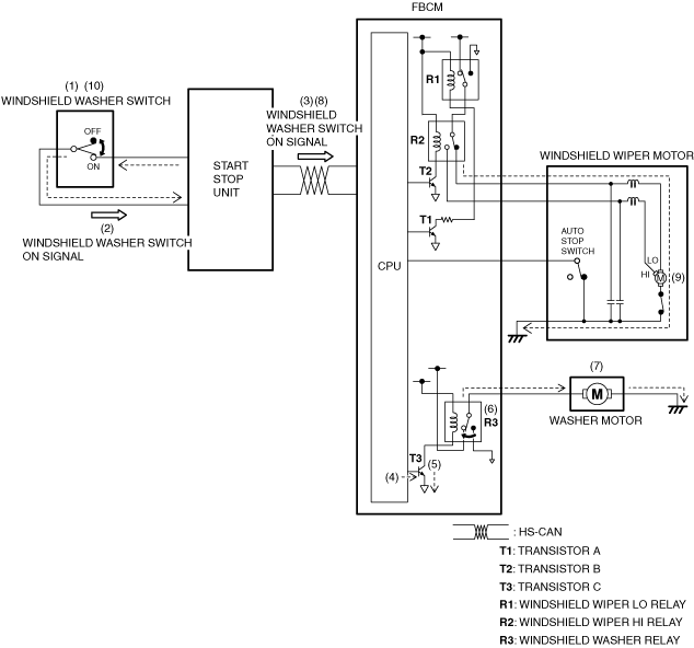
1. If the windshield washer switch is turned on (1) with the ignition switched ON (engine off or on) and the windshield wipers not operating, the start stop unit detects (2) a windshield washer switch on signal.
2. The start stop unit sends (3) the windshield washer switch on signal to the front body control module (FBCM) via CAN communication.
3. When the front body control module (FBCM) receives the windshield washer switch on signal, it turns transistor C on (4).
4. When transistor C turns on, a ground circuit with the windshield washer relay is established (5), and the windshield washer relay turns on (6).
5. When the windshield washer relay turns on, the washer motor is driven (7) and washer fluid is sprayed from the windshield washer nozzles.
6. When the front body control module (FBCM) receives (8) the windshield washer switch on signal for a certain period of time, it operates (9) the windshield wipers at low speed.
7. After the windshield washer switch is turned off (10), the windshield wipers operate 2 times at low speed and stop.
am6xun00003966
|